Changing Switch Color
The color of the HAI UPB™ Lumina Mode Controller may be changed to complement the interior décor. The HAI UPB™ Lumina Mode Controller is supplied with a white bezel. Additional colors are available; contact your HAI distributor for more information. When changing the bezel, make sure that the HAI UPB™ Lumina Mode Controller is disconnected from all power, and proceed as follows:
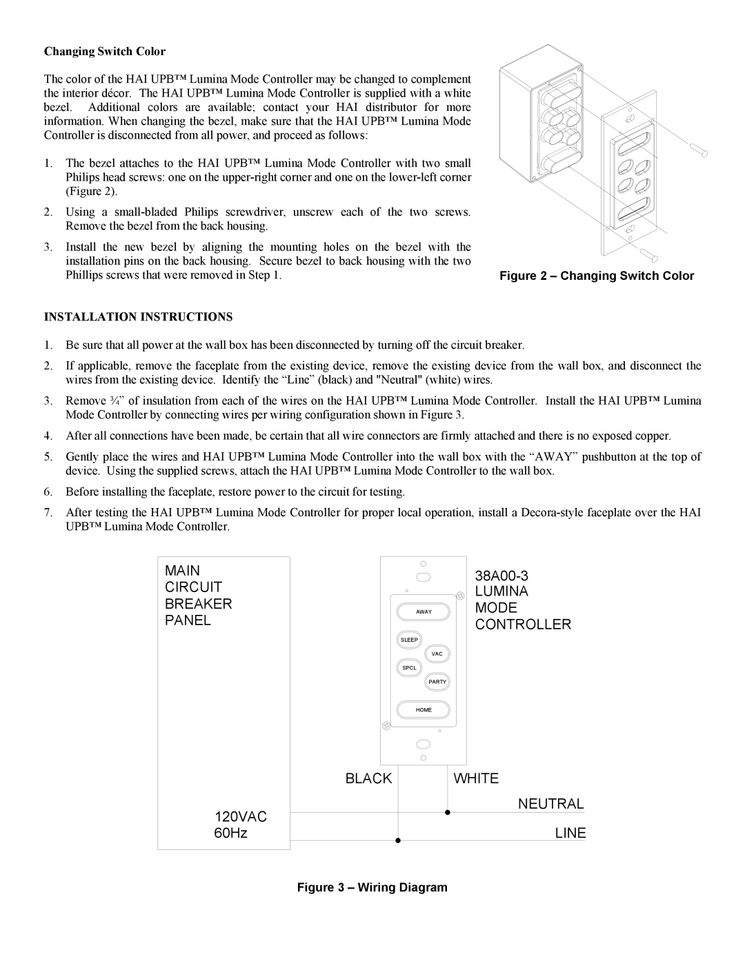
1.The bezel attaches to the HAI UPB™ Lumina Mode Controller with two small Philips head screws: one on the
2.Using a
3.Install the new bezel by aligning the mounting holes on the bezel with the installation pins on the back housing. Secure bezel to back housing with the two
Phillips screws that were removed in Step 1. | Figure 2 – Changing Switch Color |
INSTALLATION INSTRUCTIONS
1.Be sure that all power at the wall box has been disconnected by turning off the circuit breaker.
2.If applicable, remove the faceplate from the existing device, remove the existing device from the wall box, and disconnect the wires from the existing device. Identify the “Line” (black) and "Neutral" (white) wires.
3.Remove ¾” of insulation from each of the wires on the HAI UPB™ Lumina Mode Controller. Install the HAI UPB™ Lumina Mode Controller by connecting wires per wiring configuration shown in Figure 3.
4.After all connections have been made, be certain that all wire connectors are firmly attached and there is no exposed copper.
5.Gently place the wires and HAI UPB™ Lumina Mode Controller into the wall box with the “AWAY” pushbutton at the top of device. Using the supplied screws, attach the HAI UPB™ Lumina Mode Controller to the wall box.
6.Before installing the faceplate, restore power to the circuit for testing.
7.After testing the HAI UPB™ Lumina Mode Controller for proper local operation, install a
MAIN CIRCUIT BREAKER PANEL
AWAY
SLEEP
VAC
SPCL
PARTY
LUMINA
MODE CONTROLLER
HOME
BLACK | WHITE |
120VAC | NEUTRAL |
| |
60Hz | LINE |