USER-SUPPLIED PARTS
In addition to the standard tools and cables required for a video security installation, you need to provide the following items:
Qty Description
1Cat5e (or better) cable with the individual wires exposed at each end (for connecting the data interface to the matrix keyboard wallblock connector)
1Power supply; refer to Power Connection on page 16 for more information
PRODUCT SERIAL NUMBER LABEL PLACEMENT
The product serial number label helps identify your data interface and its factory configuration settings in the event that the unit requires service.
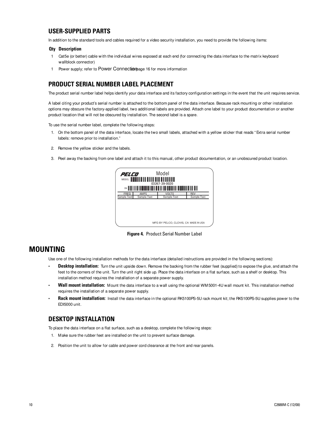
A label citing your product’s serial number is attached to the bottom panel of the data interface. Because rack mounting or other installation options may obscure the
To use the serial number label, complete the following steps:
1.On the bottom panel of the data interface, locate the two small labels, attached with a yellow sticker that reads “Extra serial number labels: remove prior to installation.”
2.Remove the yellow sticker and the labels.
3.Peel away the backing from one label and attach it to this manual, other product documentation, or an unobscured product location.
Model
MODEL
SN
| FREQ | AMPS | VOLTS | REV |
| Sample Text | Sample Text | Sample Text | Sample Text |
MFG BY PELCO, CLOVIS, CA MADE IN USA
Figure 4. Product Serial Number Label
MOUNTING
Use one of the following installation methods for the data interface (detailed instructions are provided in the following sections):
•Desktop installation: Turn the unit upside down. Remove the backing from the rubber feet (supplied) to expose the glue, and attach the feet to the corners of the unit. Turn the unit right side up. Place the data interface on a flat surface, such as a shelf or desktop. This installation method requires the installation of a separate power supply.
•Wall mount installation: Mount the data interface to a wall using the optional
•Rack mount installation: Install the data interface in the optional
DESKTOP INSTALLATION
To place the data interface on a flat surface, such as a desktop, complete the following steps:
1.Make sure the rubber feet are installed on the unit to prevent surface damage.
2.Position the unit to allow for cable and power cord clearance at the front and rear panels.
10 |
