WS5000 Advanced System Software Operation manual (C1624M) for instructions on configuring alarms in the Endura system. Refer to the matrix system documentation for instructions on configuring matrix alarms.
NOTE: Endura system cameras should not be called by alarms configured in the matrix system. The EDI5000 does not block Endura system camera number from being used in this way, but if you configure a matrix system alarm to call an Endura system camera, the camera switch will not function consistently.
•Display Mode: Select the type of video stream to be created and displayed by the data interface. You can configure the unit to display live video only, recorded video only, or both types of video. If you select both types of video (LIVEPLAYBACK), use the Live On Switch setting to set the default video display mode (live video or playback).
•Camera Offset: This value differentiates video from the matrix system (live) with video from the Endura system (either live or recorded). When a camera number lower than the offset value is selected, commands are sent to the matrix system (with the exception of the toggle video command; refer to the (Design and product specifications subject to change without notice. on page 41 for operation instructions specific to each EDI5000 model). When a camera number higher than the offset value is selected, commands are sent to the Endura system (you must assign the appropriate logical camera numbers in the Endura system; refer to Software Configuration Overview on page 20).
If the system uses Endura DVRs/NVRs to record video from the matrix system, the camera offset value is also used to map the recorded video for each matrix system camera. You must assign logical camera numbers in the Endura system for each matrix system cameras that is recorded by an Endura DVR or NVR. These logical numbers must correspond to the same logical numbers resulting from the offset value. For example, if the offset value is 1000, an operator can view recorded video from Camera 1 by selecting Camera 1001 (or by using the toggle button; refer to the (Design and product specifications subject to change without notice. on page 41 for operation instructions specific to each EDI5000 model). The new value must be a valid logical camera number in the Endura system; if not, the display does not switch.
•Script Offset: This value differentiates matrix system sequences (also known as tours) from commands that are sent to the Endura system to trigger a script. When an operator runs a sequence with a number lower than the offset value, the command is sent to the matrix system; when an operator runs a sequence with a number higher than the offset value, the command is sent to the Endura system where it triggers an Endura script. For example, if the offset value is 50, when the operator runs sequence number 55 the command is sent to the Endura system to activate script number 55. The name of the Endura script must be a unique logical number that is higher than the script offset value (refer to the Endura system documentation for instructions on configuring and naming an Endura script.).
NOTE: Endura system cameras should not be called by sequences configured in the matrix system. The EDI5000 does not block Endura system camera number from being used in this way, but if you configure a matrix system sequence or alarm to call an Endura system camera, the camera switch will not function consistently.
•Time Sync Minutes: Type the frequency (in number of minutes, between 0 and 99999) when the data interface will adjust the time and date settings on the matrix switcher. By default this value is set at 0 (zero), which disables the time sync functionality. A minimum value of 60 minutes is recommended.
•Initial Jump Back Seconds: Type the number of seconds (between 0 and 99999) that you want the video to jump back from the current time when switching to a recorded video stream; this setting does not affect live video. Note that you cannot jump back from a specific time setting on the recorded video; this command only applies to current time.
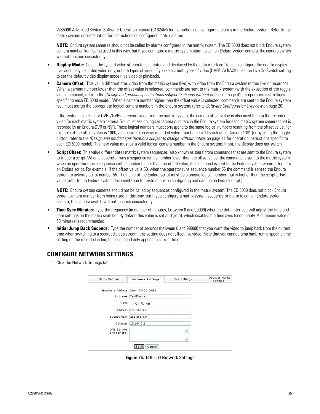
CONFIGURE NETWORK SETTINGS
1. Click the Network Settings tab.
Figure 26. EDI5000 Network Settings
25 |
