
UT15522F specifications
The Homelite UT15522F is a robust and reliable string trimmer designed for homeowners and garden enthusiasts looking to maintain their lawns and gardens with ease. This powerful trimmer is equipped with features that streamline lawn care and provide flexibility in tackling various outdoor tasks.One of the standout characteristics of the UT15522F is its 15-inch cutting width. This allows for efficient trimming of larger areas without the need for excessive passes, saving time and effort. The trimmer is powered by a 2-cycle engine that delivers reliable performance and sufficient power to handle tough grass and weeds, making it suitable for both light and heavy-duty tasks.
The UT15522F incorporates an automatic line advance system, which helps to simplify the process of replacing trimmer line. This feature ensures that the line extends only when needed, preventing unnecessary wear and reducing the frequency of line replacements. This automatic system allows users to focus on their trimming tasks without the hassle of constant adjustments.
Weight is another critical factor in the design of the UT15522F. At about 10.5 pounds, it strikes a balance between portability and stability, allowing users to maneuver the unit easily. Its ergonomic design features a comfortable handle that reduces arm strain during extended use, ensuring that lawn care becomes a less tiring task.
A vital technology in the Homelite UT15522F is its Easy Start system. This innovative feature makes starting the trimmer easy and straightforward, enhancing the overall user experience. With a simpler starting mechanism, users can get to work faster without the frustration often associated with traditional pull-start engines.
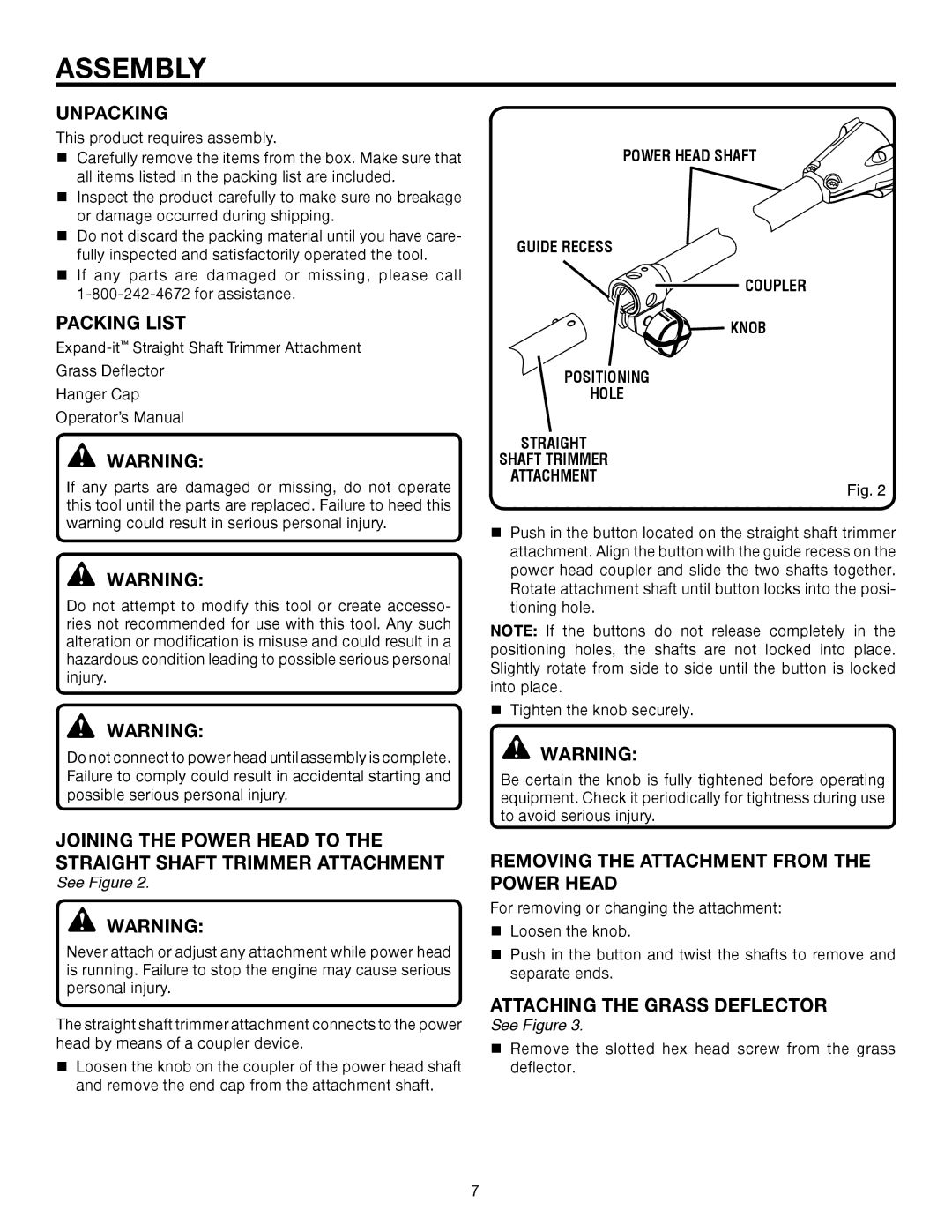
The UT15522F also comes with a variety of attachments available for purchase, making it versatile for different gardening tasks such as edging or clearing brush. The adaptability of this trimmer makes it a valuable tool in any homeowner's arsenal.
In summary, the Homelite UT15522F is a feature-rich string trimmer that combines power, ease of use, and versatility. Its 15-inch cutting width, automatic line advance, ergonomic design, and Easy Start technology position it as an excellent choice for anyone looking to maintain their outdoor spaces efficiently. Whether tackling a small garden or a sprawling lawn, the UT15522F stands ready to meet the challenge.