
5808W3 specifications
The Honeywell 5808W3 is a state-of-the-art smoke and heat detector designed for residential and commercial applications, incorporating innovative technologies to enhance safety and reliability. This advanced device integrates both photoelectric smoke detection and fixed temperature heat sensing, providing dual functionality to ensure optimal fire detection capabilities.One of the standout features of the Honeywell 5808W3 is its photoelectric sensing technology, which excels at quickly identifying smoldering fires. This type of fire can produce large amounts of smoke before bursting into flames, making early detection crucial. The 5808W3’s photoelectric sensor uses a light source that detects smoke particles, allowing it to respond more rapidly to slow-burning fires compared to traditional ionization detectors.
In addition to smoke detection, the 5808W3 boasts a fixed temperature heat sensor, which activates an alarm when the temperature reaches a predetermined threshold. This feature is particularly beneficial in environments where smoke alarms might be prone to false alarms, such as kitchens or garages.
Another significant characteristic of the Honeywell 5808W3 is its wireless communication capability. Utilizing Honeywell's 5800 series wireless technology, the detector can easily transmit alarm signals to compatible Honeywell control panels without the need for complex wiring. This wireless feature not only simplifies installations but also allows for greater flexibility in device placement, ensuring optimal performance and coverage across the property.
The 5808W3 also includes a built-in sounder that emits an audible alarm when smoke or heat is detected. The device is designed to integrate seamlessly into existing security systems, enhancing overall monitoring and response capabilities.
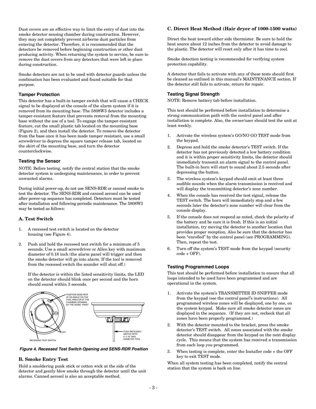
Moreover, it features a robust design that minimizes susceptibility to environmental factors, ensuring reliable operation in various conditions. The unit is also equipped with a tamper-resistant design, making it secure against unauthorized removal.
In summary, the Honeywell 5808W3 smoke and heat detector stands out due to its dual detection technologies, wireless capabilities, and robust construction. Its combination of photoelectric and heat-sensing technologies offers comprehensive protection against a wide range of fire hazards, ensuring safety and peace of mind in any setting. Whether for home use or commercial applications, the Honeywell 5808W3 is a reliable choice for fire detection needs.