Electrical Connections
4. Electrical Connections
4.1 Overview
The terminal board connections for the various Honeywell measuring instruments are given in the appropriate Figures in this section.
To avoid the possibility of AC pickup in the cell leads, separate them from all AC
ATTENTION
Do not use shielded cable except where shown in the following figures.
4.2 Instrument Wiring for 4905 Cells with Integral Cable
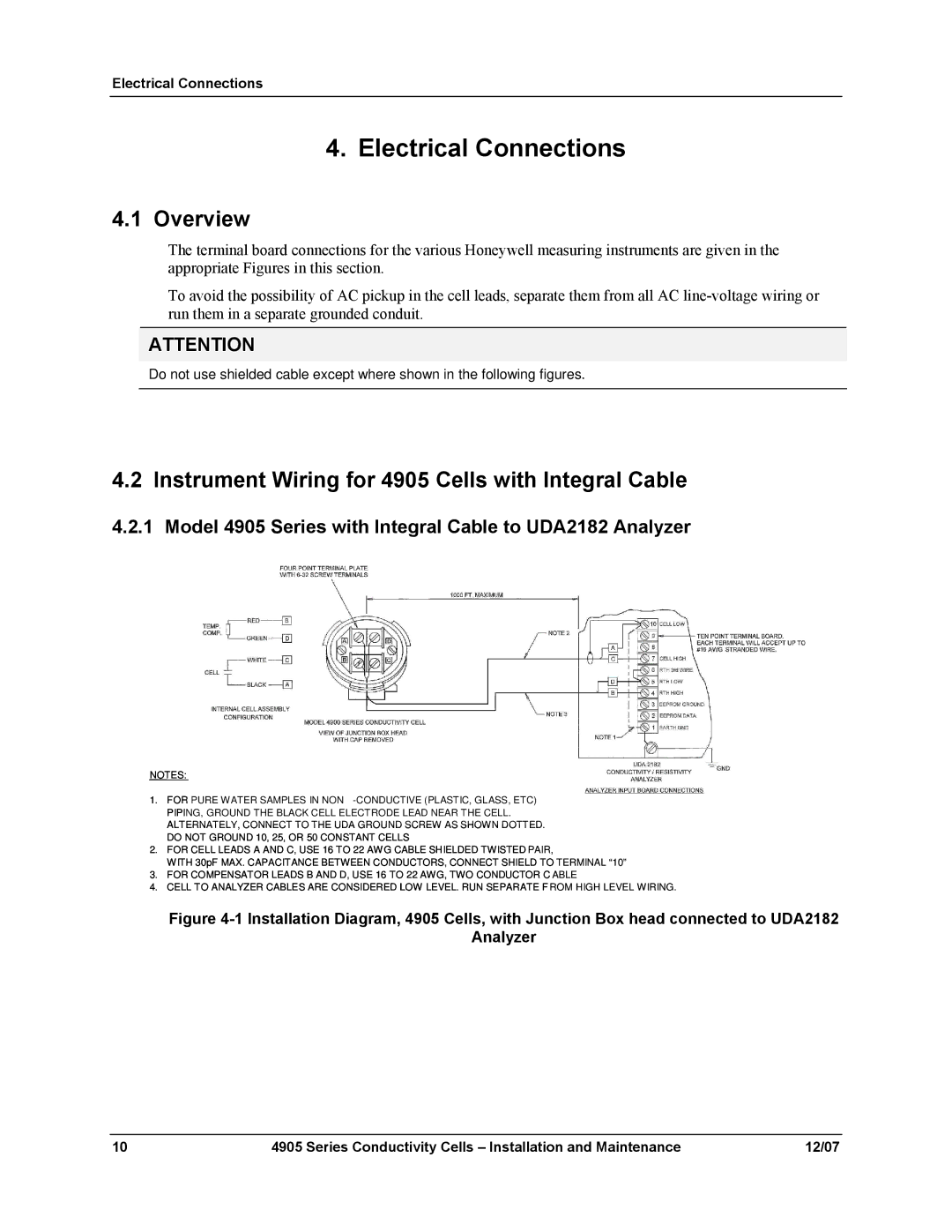
4.2.1 Model 4905 Series with Integral Cable to UDA2182 Analyzer
NOTES:
1.FOR PURE WATER SAMPLES IN NON
2.FOR CELL LEADS A AND C, USE 16 TO 22 AWG CABLE SHIELDED TWISTED PAIR,
WITH 30pF MAX. CAPACITANCE BETWEEN CONDUCTORS, CONNECT SHIELD TO TERMINAL “10”
3.FOR COMPENSATOR LEADS B AND D, USE 16 TO 22 AWG, TWO CONDUCTOR C ABLE
4. CELL TO ANALYZER CABLES ARE CONSIDERED LOW LEVEL. RUN SEPARATE F ROM HIGH LEVEL WIRING.
Figure 4-1 Installation Diagram, 4905 Cells, with Junction Box head connected to UDA2182
Analyzer
10 | 4905 Series Conductivity Cells – Installation and Maintenance | 12/07 |
