C6097A,B PRESSURE SWITCHES
WIRING
![]() WARNING
WARNING
Electrical Shock Hazard.
Can cause serious personal injury or death.
Disconnect power supply before beginning installation.
More than one disconnection can be involved.
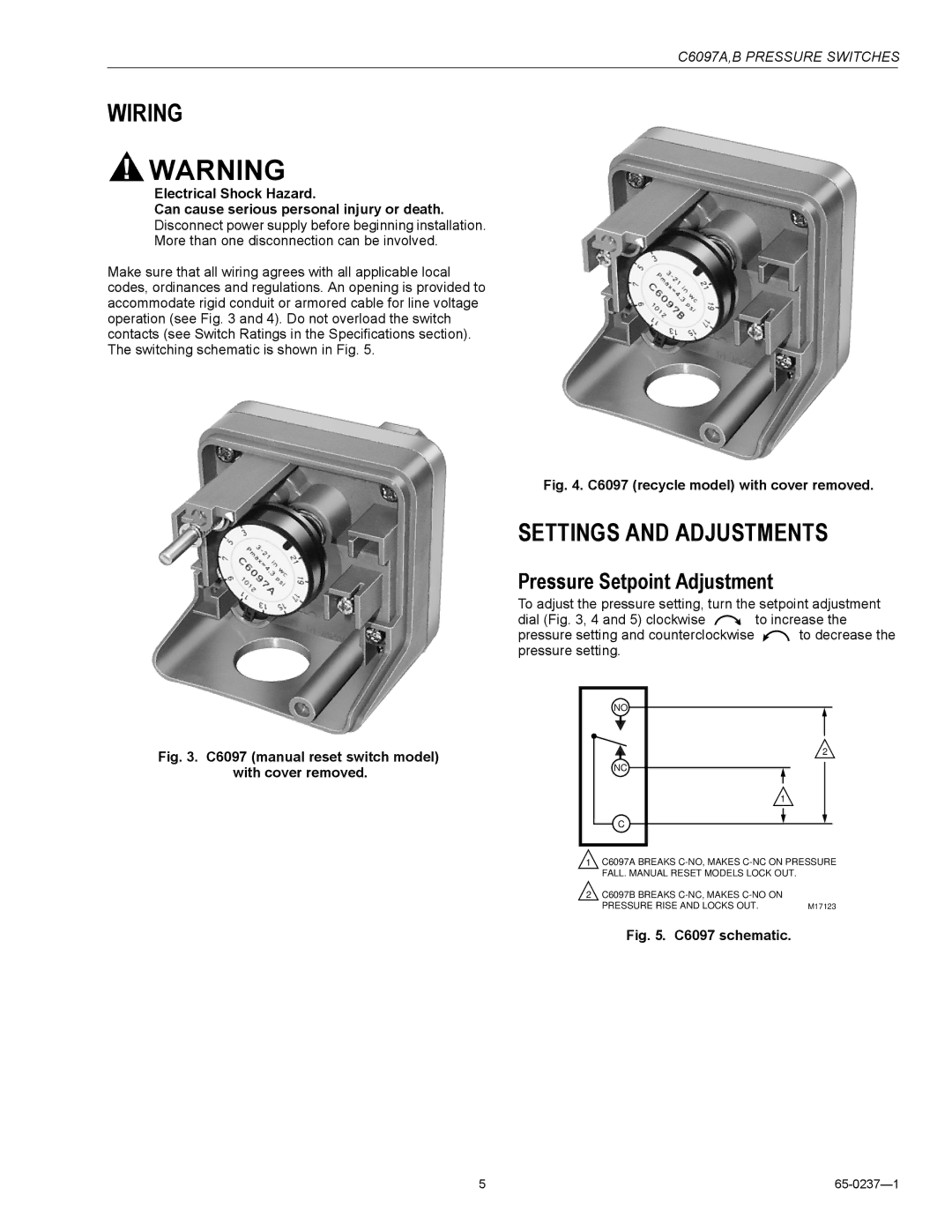
Make sure that all wiring agrees with all applicable local codes, ordinances and regulations. An opening is provided to accommodate rigid conduit or armored cable for line voltage operation (see Fig. 3 and 4). Do not overload the switch contacts (see Switch Ratings in the Specifications section). The switching schematic is shown in Fig. 5.
Fig. 3. C6097 (manual reset switch model) with cover removed.
Fig. 4. C6097 (recycle model) with cover removed.
SETTINGS AND ADJUSTMENTS
Pressure Setpoint Adjustment
To adjust the pressure setting, turn the setpoint adjustment
dial (Fig. 3, 4 and 5) clockwise ![]() to increase the
to increase the
pressure setting and counterclockwise ![]() to decrease the pressure setting.
to decrease the pressure setting.
NO |
2 |
NC |
1 |
C |
1C6097A BREAKS
2C6097B BREAKS
PRESSURE RISE AND LOCKS OUT. | M17123 |
Fig. 5. C6097 schematic.
5 |