2 Installation continued
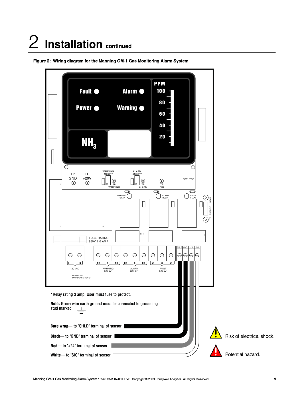
Figure 2: Wiring diagram for the Manning
| TP | TP | WARNING |
|
| ALARM |
|
|
|
|
|
|
| |
| ADJUST |
|
| ADJUST |
|
|
|
|
|
|
| |||
GND | +20V |
|
|
|
|
|
|
|
| BOT | TOP |
|
| |
7 |
|
| TP |
|
| TP |
| TP |
|
|
|
|
| |
|
|
| WARNING |
| ALARM |
| SIG |
|
|
|
|
| ||
|
|
|
| WARNING |
|
|
| ALARM |
|
| FAULT | DRAW | ||
|
|
|
|
| RELAY |
|
|
| RELAY |
|
| RELAY | ||
|
|
|
|
|
|
|
|
|
|
|
|
|
| |
|
|
|
|
|
|
|
|
|
|
|
|
|
| CURRENT |
|
|
|
|
|
|
|
|
|
|
|
|
|
| TP |
1 |
|
| 6 |
|
|
|
|
|
|
|
|
|
|
|
|
|
|
|
|
| + | C11 |
|
| + |
|
|
| + |
|
| FUSE RATING |
|
|
|
|
|
|
|
|
|
|
| |
|
| 250V 1.0 AMP |
|
|
|
|
|
|
|
|
|
|
| |
|
|
|
|
|
|
|
|
|
| SHLD | GND | +24 | SIG |
|
L | N | NO | C | NC | NO | C | NC | NO | C | NC |
|
|
|
|
| 120 VAC |
| WARNING |
|
| ALARM |
|
| FAULT |
|
|
|
|
|
|
|
| RELAY* |
|
| RELAY* |
|
| RELAY* |
|
|
|
|
|
| MODEL G/M |
|
|
|
|
|
|
|
|
|
|
|
| |
| MAINBOARD REV D |
|
|
|
|
|
|
|
|
|
|
|
| |
*Relay rating 3 amp. User must fuse to protect.
Note: Green wire earth ground must be connected to grounding stud marked
Bare wrap— to "SHLD" terminal of sensor
Black— to "GND" terminal of sensor
Red— to "+24" terminal of sensor
White— to "SIG" terminal of sensor
Risk of electrical shock.
Potential hazard.
Manning | 9 |