Honeywell 19546GM1 installation manual Installation, ALocating the Manning GM-1

Models: 19546GM1 GM-1

1 13
Download 13 pages 41.4 Kb
Page 7
Image 7
2 Installation

2 Installation

ALocating the Manning GM-1

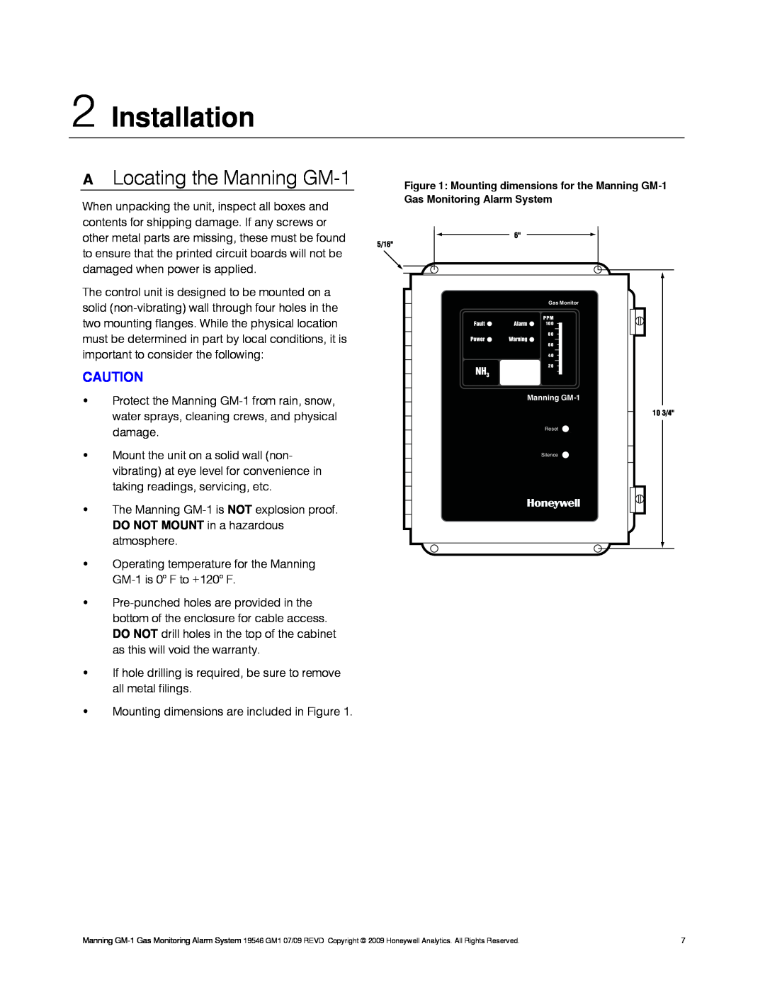
Figure 1: Mounting dimensions for the Manning GM-1

When unpacking the unit, inspect all boxes and contents for shipping damage. If any screws or other metal parts are missing, these must be found to ensure that the printed circuit boards will not be damaged when power is applied.

5/16"

Gas Monitoring Alarm System

6"

The control unit is designed to be mounted on a solid (non-vibrating) wall through four holes in the two mounting flanges. While the physical location must be determined in part by local conditions, it is important to consider the following:

CAUTION

Protect the Manning GM-1 from rain, snow, water sprays, cleaning crews, and physical damage.

Mount the unit on a solid wall (non- vibrating) at eye level for convenience in taking readings, servicing, etc.

The Manning GM-1 is NOT explosion proof. DO NOT MOUNT in a hazardous atmosphere.

Gas Monitor

Manning GM-1

Reset

24 1/4"

Silence

10 3/4"

Operating temperature for the Manning GM-1 is 0o F to +120o F.

Pre-punched holes are provided in the bottom of the enclosure for cable access. DO NOT drill holes in the top of the cabinet as this will void the warranty.

If hole drilling is required, be sure to remove all metal filings.

Mounting dimensions are included in Figure 1.

Manning GM-1 Gas Monitoring Alarm System 19546 GM1 07/09 REVD Copyright © 2009 Honeywell Analytics. All Rights Reserved.

7

Page 7
Image 7
Honeywell 19546GM1 installation manual Installation, ALocating the Manning GM-1