3 Operation
ADisplay Panel
A
The Warning LED indicates the warning level as determined by the warning setpoint has been exceeded. The Warning LED and Warning Relay operate together and never latch.
The Alarm LED indicates the alarm level as determined by the alarm setpoint has been exceeded. The Alarm LED and Alarm Relay are independently latchable or
The Power LED indicates power to the monitoring unit. This LED will flash during the one minute power up delay indicating that all relays are held in the normal condition to allow for sensor stabilization during power up.
The Fault LED indicates a signal input of less than
1.4mA (0.14 volts) at TP Sig. The Fault LED and Fault Relay always latch.
BReset and Silence Switches
Pushing the Reset switch will reset the fault light, fault relay, alarm light, and alarm relay. If either condition still exists, the appropriate light and relay will return to its tripped state after a time delay.
Pushing the Silence switch will silence the horn on the bottom of the Manning
CDIP Switch Setting
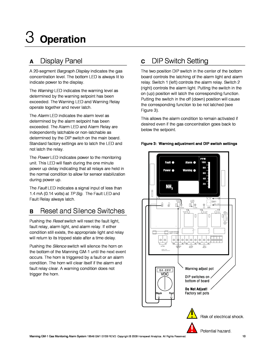
The two position DIP switch in the center of the bottom board controls the latching of the alarm light and alarm relay. Switch 1 (left) controls the alarm relay. Switch 2 (right) controls the alarm light. Putting the switch in the on (up) position will latch the corresponding function. Putting the switch in the off (down) position will cause the corresponding function to be not latched (see Figure 3).
This allows the alarm condition to remain activated if desired even if the gas concentration goes back to below the setpoint.
Figure 3: Warning adjustment and DIP switch settings
TP | WARNING | ALARM |
| 1 2 | SW1 |
|
TP | ADJUST |
|
| |||
| ADJUST |
|
|
|
| |
GND | +20V |
|
|
| BOT TOP |
|
7 | TP | TP | TP | AA |
|
|
| WARNING | ALARM | SIG |
|
| |
| WARNING |
| ALARM |
| FAULT | DRAW |
| RELAY |
| RELAY |
| RELAY | |
|
|
|
|
|
| CURRENT |
|
|
|
|
|
| TP |
1 | 6 |
|
|
|
|
|
|
| + C11 |
| + |
| + |
FUSE RATING 250V 1.0 AMP
SHLD GND | +24 | SIG |
L | N | NO | C | NC | NO | C | NC | NO | C | NC |
| 120 VAC |
| WARNING |
|
| ALARM |
|
| FAULT |
|
|
|
| RELAY* |
|
| RELAY* |
|
| RELAY* |
|
MODEL G/M
MAINBOARD REV D
|
|
|
|
| Warning adjust pot |
| 0.4 - 2.0 V |
| |||
|
|
| |||
|
|
|
|
| |
| VDC |
|
| DIP switches on | |
|
|
|
|
| |
|
|
|
|
| bottom of board |
|
|
|
|
| Do Not Adjust! |
|
|
|
|
| |
Black | Red | Factory set pots | |||
- |
| + |
|
| |
|
|
|
|
|
|
Risk of electrical shock.
Potential hazard.
Manning | 10 |