Manuals
/
Honeywell
/
Household Appliance
/
Home Security System
Honeywell
PRO22ENC1, PRO22ENC2
installation manual
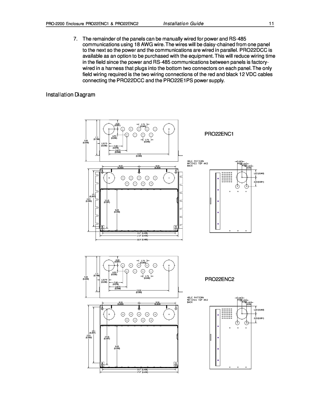
Installation Diagram
Models:
PRO22ENC1
PRO22ENC2
1
10
23
23
Download
23 pages
2.79 Kb
7
8
9
10
11
12
13
14
Specs
Install
Warranty
Dimension
UL1076 Setup
Unpacking Procedure
Power Supply Dimensions
Page 10
Image 10
Page 9
Page 11
Page 10
Image 10
Page 9
Page 11
Contents
Part Number PRO22ENC1 PRO22ENC2
PRO-2200 Enclosure Installation Manual
TD1138 rev0801
Contents
Fire Safety and Liability Notice
Warnings and Cautions
BUT NOT BOTH
Page
Disclaimer
Unpacking Procedure
Product Liability Mutual Indemnification
Shipping Instructions
Limited Warranty
To ship equipment back to Engineered Systems
Confidentiality
PRO-2200Enclosure
Description
Maintenance
Dimensions
Power Supply
Installation Instructions
Installation Diagram
PC Minimum Requirements
UL1076 Setup
Receiving Unit minimum configuration
Peripheral Hardware Requirements
A.Select Full Installation
Procedures
Other UL1075 Notes
B.Select SQL for Database
Second PC Installation
Enterprise Manager Setup
DTS Package Verification
Pre-RedundancyVerification
Interim Steps Before Full Redundancy Verification
Example #1
Power Supply Dimensions
Redundant Test Examples
Example #2
Dimensions
Installation Diagram
Power Supply Enclosure
Installation Guide
Installation
Installation Instructions
Cable Specifications
ESG Cable Part Numbers
Installation Guide
PRO-2200Enclosure PRO22ENC1 & PRO22ENC2
Installation Guide
PRO-2200Enclosure PRO22ENC1 & PRO22ENC2
Installation Guide
PRO-2200Enclosure PRO22ENC1 & PRO22ENC2
Honeywell Security & Data Collection
2700 Blankenbaker Pkwy, Suite Louisville, KY
Top
Page
Image
Contents