INSTALLATION CHECKLIST ///
■XG1000 Controller and a Honeywell Bridge
■6160 Alpha panel as a debugging tool
■Confirm address 22 is open and configured as a keypad device.
Please note that if 22 is already is use, the existing keypad will need to be moved to a different address
■Remote account username and password
INSTALL & VALIDATE XG1000 CONTROLLER ///
1.Locate the customer’s external internet connection and the
XG1OOO CONTROLLER
1 | 2 | 3 | 4 |
|
|
|
|
| INTERNET |
| LAN |
| WAN | LAN |
| ROUTER | DSL/CABLE MODEM | ||
| (NOT INCLUDED) | (NOT INCLUDED) | ||
2.Connect XG1000 Controller to power and verify the following:
■The XG1000 ‘X’ power LED is lighted BLUE
If the power LED is not lighted, please
■The XG1000 LAN/Link LED is lighted GREEN
If the LAN/Link LED does not light check the Ethernet connection and/or try using a different Ethernet cable (see Troubleshooting Section)
3.Wait up to 3 minutes for the XG1000 Controller to initialize.
4.Check and confirm LED marked ‘REM’ is solid GREEN (REM LED is the health indicator for remote access).
| DEV |
|
| LAN |
|
|
|
|
|
|
|
|
|
|
ACT | STAT | REM | ACT | LINK |
REMOTE CONNECTIVITY | LAN LINK | POWER INDICATOR |
HONEYWELL BRIDGE INSTALLATION PROCEDURE ///
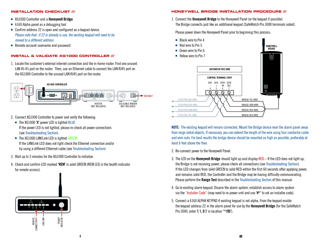
1.Connect the Honeywell Bridge to the Honeywell Panel (or the keypad if possible)
The Bridge connects just like an additional keypad (SafeWatch Pro 3000 terminals noted). Please power down the Honeywell Panel prior to beginning this process:
■Black wire to Pin 4
■ | Red wire to Pin 5 |
|
| HONEYWELL |
■ | Green wire to Pin 6 |
|
| BRIDGE |
|
|
| ||
■ | Yellow wire to Pin 7 |
|
|
|
| SAFEWATCH PRO 3000 | |||
| CONTROL TERMINAL STRIP | |||
| AUX. | AUX. | DATA | DATA |
| – | + | IN | OUT |
| 4 | 5 | 6 | 7 |
| TO KEYPAD BLK WIRE |
|
| BRIDGE YEL WIRE |
| TO KEYPAD RED WIRE |
|
| BRIDGE GRN WIRE |
| TO KEYPAD GRN WIRE |
|
| BRIDGE RED WIRE |
| TO KEYPAD YEL WIRE |
|
| BRIDGE BLK WIRE |
NOTE: The existing keypad will remain connected. Mount the Bridge device near the alarm panel away from large metal objects. If necessary, you can extend the length of the wire using four conductor cable and wire nuts. For best results the bridge device should be mounted as high as possible, preferably at least 6 feet above the floor.
2.Re-connect power to the Honeywell Panel.
3.The LED on the Honeywell Bridge should light up and display RED – If the LED does not light up, the Bridge is not receiving power, please check all connections (see Troubleshooting Section).
If the LED changes from solid GREEN to solid RED within the first 60 seconds after applying power, and remains solid RED, the Controller and the Bridge may be having difficulty communicating. Please perform the Range Test described in the Troubleshooting Section of this manual.
4.Go to existing alarm keypad. Disarm the alarm system, establish access to alarm system via the “Installer Code” (may need to
5.Connect a 6160 ALPHA KEYPAD if existing keypad is not alpha. From the keypad enable
the keypad address 22 in the alarm panel for use by the Honeywell Bridge (for the SafeWatch Pro 3000, enter ‘[ 1, 0 ]’ in location ‘*195’).
I | 2 |