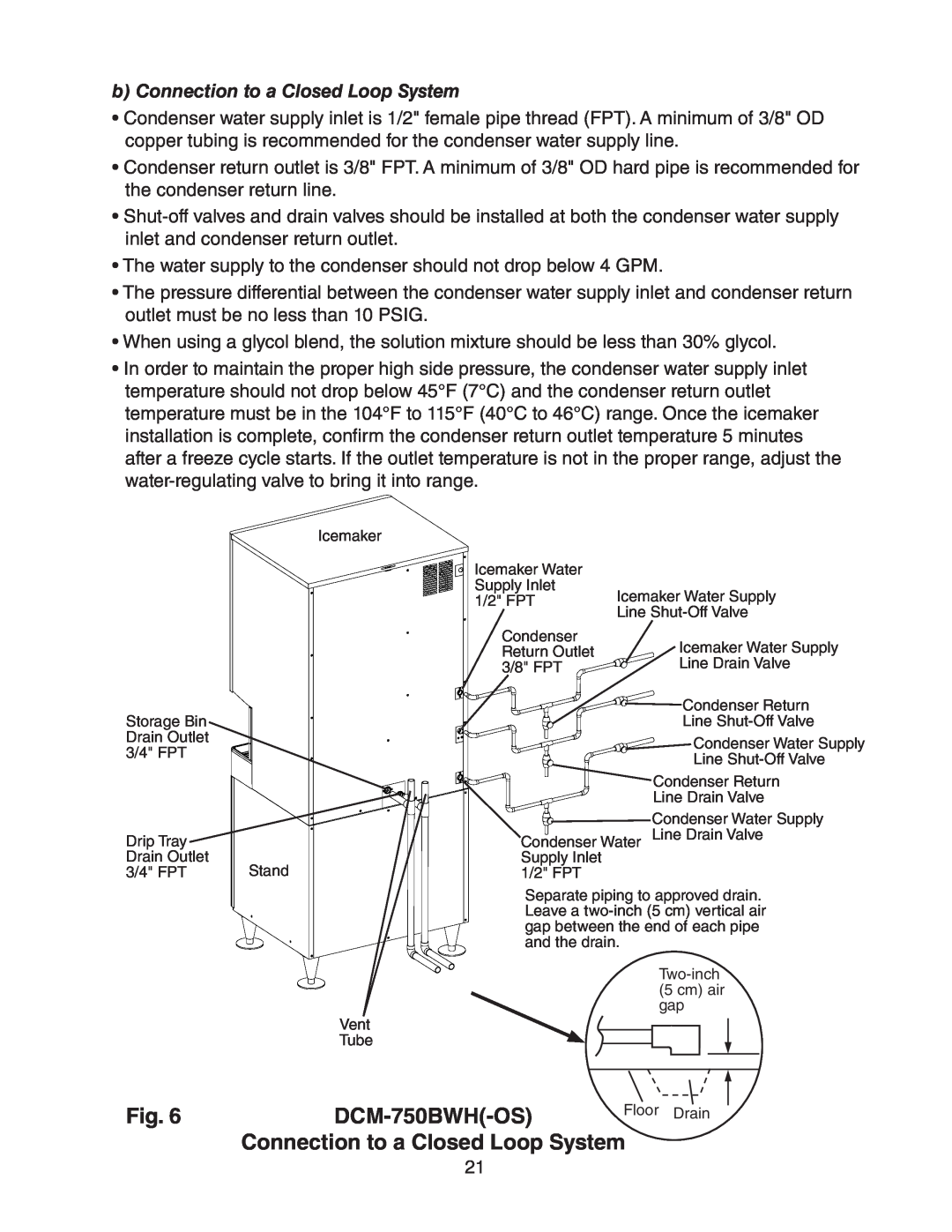
b) Connection to a Closed Loop System
•Condenser water supply inlet is 1/2" female pipe thread (FPT). A minimum of 3/8" OD copper tubing is recommended for the condenser water supply line.
•Condenser return outlet is 3/8" FPT. A minimum of 3/8" OD hard pipe is recommended for the condenser return line.
•
•The water supply to the condenser should not drop below 4 GPM.
•The pressure differential between the condenser water supply inlet and condenser return outlet must be no less than 10 PSIG.
•When using a glycol blend, the solution mixture should be less than 30% glycol.
•In order to maintain the proper high side pressure, the condenser water supply inlet temperature should not drop below 45°F (7°C) and the condenser return outlet temperature must be in the 104°F to 115°F (40°C to 46°C) range. Once the icemaker installation is complete, confirm the condenser return outlet temperature 5 minutes after a freeze cycle starts. If the outlet temperature is not in the proper range, adjust the water‑regulating valve to bring it into range.
Storage Bin
Drain Outlet
3/4" FPT
Drip Tray
Drain Outlet
3/4" FPT
Icemaker
Stand
Vent
Tube
Icemaker Water |
|
Supply Inlet | Icemaker Water Supply |
1/2" FPT | |
| Line |
Condenser | Icemaker Water Supply |
Return Outlet | |
3/8" FPT | Line Drain Valve |
| Condenser Return |
| Line |
| Condenser Water Supply |
| Line |
| Condenser Return |
| Line Drain Valve |
![]()
![]()
![]()
![]()
![]() Condenser Water Supply Condenser Water Line Drain Valve Supply Inlet
Condenser Water Supply Condenser Water Line Drain Valve Supply Inlet
1/2" FPT
Separate piping to approved drain. Leave a
Fig. 6 |
| Floor Drain |
| Connection to a Closed Loop System | |
21