wall to the ceiling with a pencil. It will help the installation operations.
2.Apply the perforation diagram to the wall: The centre vertical line printed on the perforation diagram must correspond to the centre line drawn on the wall. In addition, the lower edge of the perforation diagram must correspond to the lower edge of the hood: keeping mind that the lower part of the hood, once installation is completed, must distance at least 50 cm from the cooking surface in case of electric plates and 65 cm in case of gas rings or mixed tops.
3.Place the support bracket on the perforation diagram making it coincide with the rectangle marked out. Mark the two external holes and make the holes. Remove the peroration diagram, insert two wall dowels and fix the support bracket of the hood with two 5x45mm screws.
4.Hang up the suction unit.
5.Adjust the distance of the suction unit from the wall.
6.Adjust the horizontal setting of the suction unit.
7.Mark the hole for definitively fixing the suction unit from inside the suction unit with a pencil.
8.Remove the suction unit from the bracket.
9.Make a hole at the marked point (Ø8mm - see operation 7).
10.Insert 1 wall dowel.
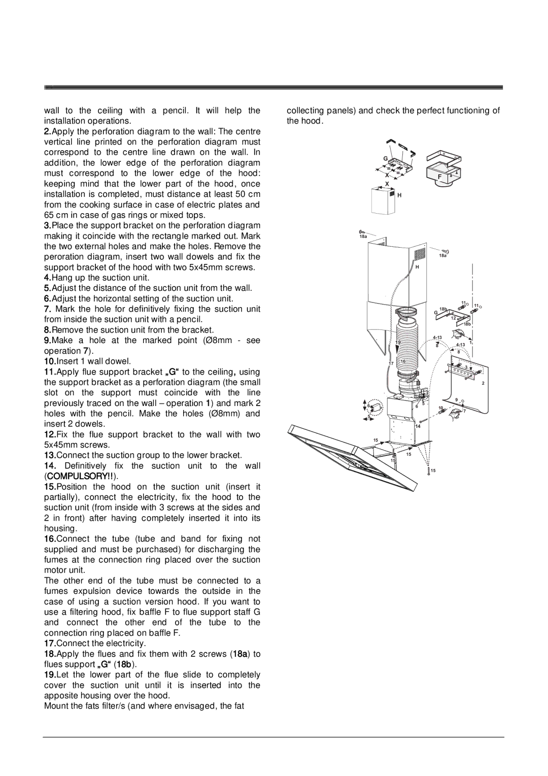
11.Apply flue support bracket „G“ to the ceiling, using the support bracket as a perforation diagram (the small slot on the support must coincide with the line previously traced on the wall – operation 1) and mark 2 holes with the pencil. Make the holes (Ø8mm) and insert 2 dowels.
12.Fix the flue support bracket to the wall with two 5x45mm screws.
13.Connect the suction group to the lower bracket.
14.Definitively fix the suction unit to the wall (COMPULSORY!!).
15.Position the hood on the suction unit (insert it partially), connect the electricity, fix the hood to the suction unit (from inside with 3 screws at the sides and
2in front) after having completely inserted it into its housing.
16.Connect the tube (tube and band for fixing not supplied and must be purchased) for discharging the fumes at the connection ring placed over the suction motor unit.
The other end of the tube must be connected to a fumes expulsion device towards the outside in the case of using a suction version hood. If you want to use a filtering hood, fix baffle F to flue support staff G and connect the other end of the tube to the connection ring placed on baffle F.
17.Connect the electricity.
18.Apply the flues and fix them with 2 screws (18a) to flues support „G“ (18b).
19.Let the lower part of the flue slide to completely cover the suction unit until it is inserted into the apposite housing over the hood.
Mount the fats filter/s (and where envisaged, the fat
collecting panels) and check the perfect functioning of | K | ||||
the hood. |
|
|
|
| |
|
|
|
|
| |
G |
|
|
|
|
|
= | = | F |
|
|
|
X |
|
|
|
| |
X |
|
|
|
|
|
| H |
|
|
|
|
18a |
|
|
|
|
|
|
| 18a |
|
|
|
|
| H |
|
|
|
|
|
| 11 | 11 |
|
|
| G 18b |
|
| |
|
| 12 |
|
| |
|
|
|
|
| |
|
|
| 18b |
|
|
198![]()
|
| 8 |
17 | 16 |
|
| 3 | |
|
| |
| B | 2 |
|
| 5 |
| 9 |
6 | 6 | 10 | 7 | |
|
|
| ||
|
|
|
| |
5 |
|
|
|
|
| 14 |
|
|
|
| 15 |
|
|
|
| 15 |
|
|
|
| 15 |
|
|
|
|
|
| 15 |
|