Maintenance & Service Guide
Presario 1800 Series
Models: 1805 and 1810
Home Page Notice Preface Product Description Troubleshooting Illustrated Parts Catalog Removal & Replacement Procedures Specifications Pin Assignments Battery Pack Operations
Connector Pin Assignments
This appendix provides connector pin assignment tables for Compaq Presario 1800 Series Portable Computers. For more information on connectors, refer to the section on Rear Connectors.
NOTE: The signals in all tables of this appendix are considered active high unless otherwise indicated by an asterisk (*).
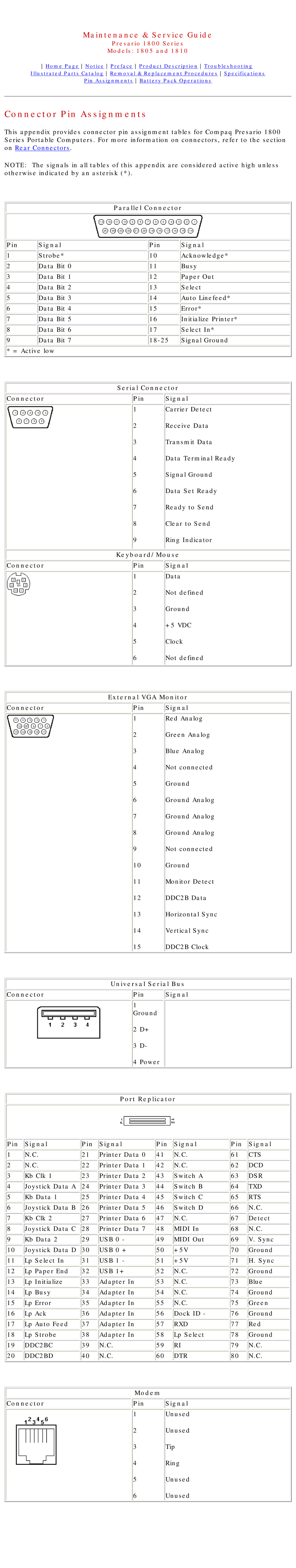
Parallel Connector
Pin | Signal | Pin | Signal |
1 | Strobe* | 10 | Acknowledge* |
2 | Data Bit 0 | 11 | Busy |
3 | Data Bit 1 | 12 | Paper Out |
4 | Data Bit 2 | 13 | Select |
5 | Data Bit 3 | 14 | Auto Linefeed* |
6 | Data Bit 4 | 15 | Error* |
7 | Data Bit 5 | 16 | Initialize Printer* |
8 | Data Bit 6 | 17 | Select In* |
9 | Data Bit 7 | Signal Ground |
![]() * = Active low
* = Active low
| Serial Connector | |
Connector | Pin | Signal |
1Carrier Detect
2Receive Data
3Transmit Data
4Data Terminal Ready
5Signal Ground
6Data Set Ready
7Ready to Send
8Clear to Send
9Ring Indicator
Keyboard/Mouse
Connector | Pin | Signal |
1Data
2Not defined
3Ground
4+5 VDC
5Clock
6Not defined
External VGA Monitor
Connector | Pin | Signal |
1Red Analog
2Green Analog
3Blue Analog
4Not connected
5Ground
6Ground Analog
7Ground Analog
8Ground Analog
9Not connected
10Ground
11Monitor Detect
12DDC2B Data
13Horizontal Sync
14Vertical Sync
15DDC2B Clock
Universal Serial Bus
Connector | Pin | Signal |
1 Ground
2D+
3D-
4Power
Port Replicator
Pin | Signal | Pin | Signal | Pin | Signal | Pin | Signal |
1 | N.C. | 21 | Printer Data 0 | 41 | N.C. | 61 | CTS |
2 | N.C. | 22 | Printer Data 1 | 42 | N.C. | 62 | DCD |
3 | Kb Clk 1 | 23 | Printer Data 2 | 43 | Switch A | 63 | DSR |
4 | Joystick Data A | 24 | Printer Data 3 | 44 | Switch B | 64 | TXD |
5 | Kb Data 1 | 25 | Printer Data 4 | 45 | Switch C | 65 | RTS |
6 | Joystick Data B | 26 | Printer Data 5 | 46 | Switch D | 66 | N.C. |
7 | Kb Clk 2 | 27 | Printer Data 6 | 47 | N.C. | 67 | Detect |
8 | Joystick Data C | 28 | Printer Data 7 | 48 | MIDI In | 68 | N.C. |
9 | Kb Data 2 | 29 | USB 0 - | 49 | MIDI Out | 69 | V. Sync |
10 | Joystick Data D | 30 | USB 0 + | 50 | +5V | 70 | Ground |
11 | Lp Select In | 31 | USB 1 - | 51 | +5V | 71 | H. Sync |
12 | Lp Paper End | 32 | USB 1+ | 52 | N.C. | 72 | Ground |
13 | Lp Initialize | 33 | Adapter In | 53 | N.C. | 73 | Blue |
14 | Lp Busy | 34 | Adapter In | 54 | N.C. | 74 | Ground |
15 | Lp Error | 35 | Adapter In | 55 | N.C. | 75 | Green |
16 | Lp Ack | 36 | Adapter In | 56 | Dock ID - | 76 | Ground |
17 | Lp Auto Feed | 37 | Adapter In | 57 | RXD | 77 | Red |
18 | Lp Strobe | 38 | Adapter In | 58 | Lp Select | 78 | Ground |
19 | DDC2BC | 39 | N.C. | 59 | RI | 79 | N.C. |
20 | DDC2BD | 40 | N.C. | 60 | DTR | 80 | N.C. |
Modem
Connector | Pin | Signal |
1Unused
2Unused
3Tip
4Ring
5Unused
6Unused