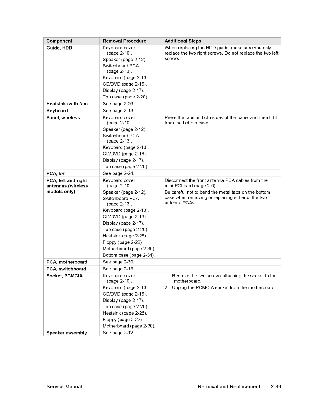
2550CA, 2542EA, 2562AP, 2555AP, 2136AD specifications
The HP 2135US is a versatile all-in-one desktop computer designed to meet the needs of home and small office users. This robust machine is particularly attractive for individuals who seek a blend of performance, aesthetics, and user-friendly features.At the heart of the HP 2135US is its powerful Intel Core processor. This series of CPUs provides reliable performance for multitasking and productivity tasks, ensuring smooth operation whether you're working on documents, browsing the web, or streaming multimedia content. Complementing the processor is a competent amount of RAM, allowing users to run multiple applications simultaneously without experiencing slowdowns.
The computer features a vibrant display that brings visuals to life. With high resolution and excellent color accuracy, the HP 2135US is ideal for photo editing, video playback, and gaming. The screen's size also contributes to an immersive experience, making it suitable for both leisure and professional uses.
Storage is another significant feature of the HP 2135US. It comes equipped with a sizeable hard drive, providing ample space for files, applications, and media libraries. Furthermore, the device offers options for solid-state drives, which enhance the system's speed and responsiveness. This blend of storage solutions ensures that users can choose configurations that best fit their needs.
Connectivity is a strong suit of the HP 2135US, as it includes a range of ports and wireless options. Multiple USB ports allow for easy connection of peripherals such as printers, keyboards, and external storage devices. Additionally, integrated Wi-Fi and Bluetooth capabilities enable seamless networking and device pairing, enhancing the overall user experience.
The integrated graphics in the HP 2135US ensures decent performance for everyday tasks and light gaming. Combined with its multimedia features, the computer serves as a capable entertainment hub for users who enjoy watching movies or playing games.
In terms of design, the HP 2135US boasts a sleek, modern aesthetic that fits well in any environment. Its compact form factor makes it space-efficient, an important consideration for users with limited workspace. The ergonomics of the design also contribute to comfortable usage over extended periods.
To sum up, the HP 2135US represents a blend of performance, connectivity, and design sophistication. Its comprehensive set of features makes it an excellent choice for users seeking an all-in-one solution for both work and play, proving itself to be a worthy addition to any modern workspace or home office setup.
