Specifications Information and Repair Parts Manual | |
|
|
Please read and save this Repair Parts Manual. Read this manual and the General Operating Instructions carefully before attempting to assemble, install, operate or maintain the product described. Protect yourself and others by observing all safety information. The Safety Instructions are contained in the General Operating Instructions. Failure to comply with the safety instructions accompanying this product could result in personal injury and/or property damage! Retain instructions for future reference. AMT reserves the right to discontinue any model or change specifications at any time without incurring any obligation.
©2006 American Machine & Tool Co., Inc. of PA, A Subsidiary of The
Periodic maintenance and inspection is required on all pumps to insure proper operation. Unit must be clear of debris and sediment. Inspect for leaks and loose bolts. Failure to do so voids warranty.
1 Inch Self-Priming Centrifugal Pumps
Refer to pump manual
Description
These centrifugal pumps are
Maintenance
Make certain that power source is disconnected before
attempting to service or disassemble any components! If power disconnect is
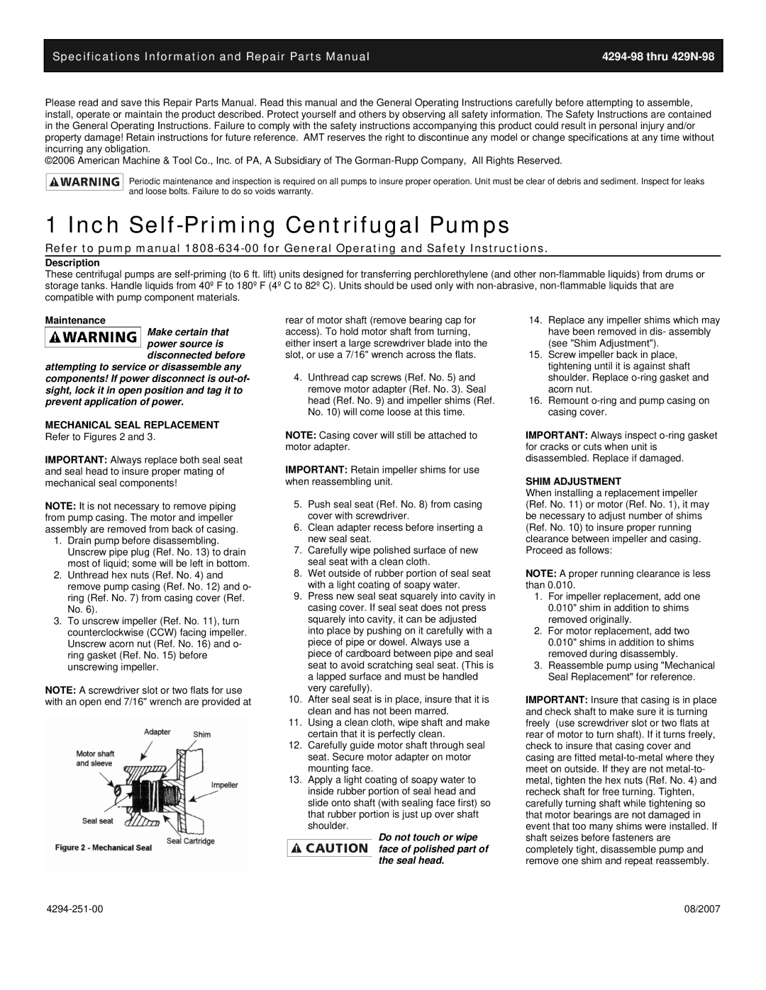
MECHANICAL SEAL REPLACEMENT Refer to Figures 2 and 3.
IMPORTANT: Always replace both seal seat and seal head to insure proper mating of mechanical seal components!
NOTE: It is not necessary to remove piping from pump casing. The motor and impeller assembly are removed from back of casing.
1.Drain pump before disassembling. Unscrew pipe plug (Ref. No. 13) to drain most of liquid; some will be left in bottom.
2.Unthread hex nuts (Ref. No. 4) and remove pump casing (Ref. No. 12) and o- ring (Ref. No. 7) from casing cover (Ref. No. 6).
3.To unscrew impeller (Ref. No. 11), turn counterclockwise (CCW) facing impeller. Unscrew acorn nut (Ref. No. 16) and o- ring gasket (Ref. No. 15) before unscrewing impeller.
NOTE: A screwdriver slot or two flats for use with an open end 7/16" wrench are provided at
rear of motor shaft (remove bearing cap for access). To hold motor shaft from turning, either insert a large screwdriver blade into the slot, or use a 7/16" wrench across the flats.
4.Unthread cap screws (Ref. No. 5) and remove motor adapter (Ref. No. 3). Seal head (Ref. No. 9) and impeller shims (Ref. No. 10) will come loose at this time.
NOTE: Casing cover will still be attached to motor adapter.
IMPORTANT: Retain impeller shims for use when reassembling unit.
5.Push seal seat (Ref. No. 8) from casing cover with screwdriver.
6.Clean adapter recess before inserting a new seal seat.
7.Carefully wipe polished surface of new seal seat with a clean cloth.
8.Wet outside of rubber portion of seal seat with a light coating of soapy water.
9.Press new seal seat squarely into cavity in casing cover. If seal seat does not press squarely into cavity, it can be adjusted into place by pushing on it carefully with a piece of pipe or dowel. Always use a piece of cardboard between pipe and seal seat to avoid scratching seal seat. (This is a lapped surface and must be handled very carefully).
10.After seal seat is in place, insure that it is clean and has not been marred.
11.Using a clean cloth, wipe shaft and make certain that it is perfectly clean.
12.Carefully guide motor shaft through seal seat. Secure motor adapter on motor mounting face.
13.Apply a light coating of soapy water to inside rubber portion of seal head and slide onto shaft (with sealing face first) so that rubber portion is just up over shaft shoulder.
Do not touch or wipe face of polished part of the seal head.
14.Replace any impeller shims which may have been removed in dis- assembly (see "Shim Adjustment").
15.Screw impeller back in place, tightening until it is against shaft shoulder. Replace
16.Remount
IMPORTANT: Always inspect
SHIM ADJUSTMENT
When installing a replacement impeller (Ref. No. 11) or motor (Ref. No. 1), it may be necessary to adjust number of shims (Ref. No. 10) to insure proper running clearance between impeller and casing. Proceed as follows:
NOTE: A proper running clearance is less than 0.010.
1.For impeller replacement, add one 0.010" shim in addition to shims removed originally.
2.For motor replacement, add two 0.010" shims in addition to shims removed during disassembly.
3.Reassemble pump using "Mechanical Seal Replacement" for reference.
IMPORTANT: Insure that casing is in place and check shaft to make sure it is turning freely (use screwdriver slot or two flats at rear of motor to turn shaft). If it turns freely, check to insure that casing cover and casing are fitted
08/2007 |