LED Codes
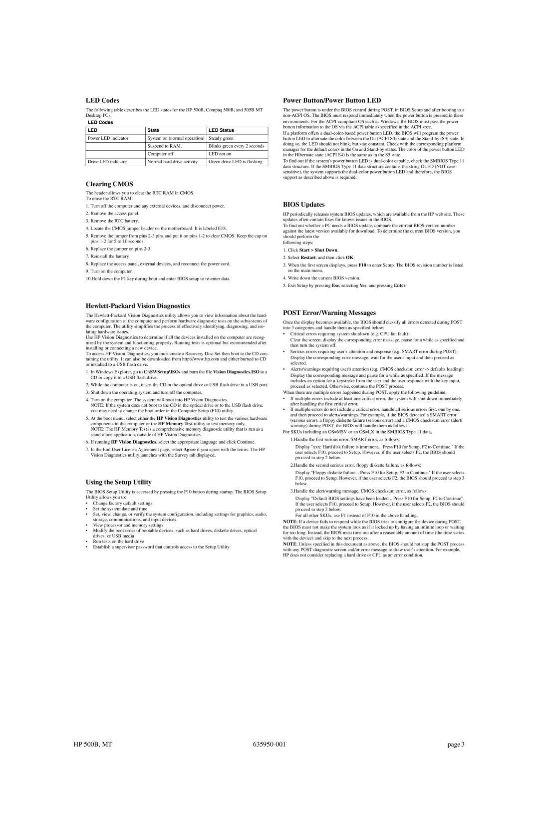
The following table describes the LED states for the HP 500B, Compaq 500B, and 505B MT Desktop PCs.
LED Codes |
|
|
LED | State | LED Status |
|
|
|
Power LED indicator | System on (normal operation) | Steady green |
|
|
|
| Suspend to RAM. | Blinks green every 2 seconds |
|
|
|
| Computer off | LED not on |
|
|
|
Drive LED indicator | Normal hard drive activity | Green drive LED is flashing |
|
|
|
Clearing CMOS
The header allows you to clear the RTC RAM in CMOS.
To erase the RTC RAM:
1.Turn off the computer and any external devices, and disconnect power.
2.Remove the access panel.
3.Remove the RTC battery.
4.Locate the CMOS jumper header on the motherboard. It is labeled E18.
5.Remove the jumper from pins
6.Replace the jumper on pins
7.Reinstall the battery.
8.Replace the access panel, external devices, and reconnect the power cord.
9.Turn on the computer.
10.Hold down the F1 key during boot and enter BIOS setup to
Power Button/Power Button LED
The power button is under the BIOS control during POST, in BIOS Setup and after booting to a
If a platform offers a
To find out if the system's power button LED is
BIOS Updates
HP periodically releases system BIOS updates, which are available from the HP web site. These updates often contain fixes for known issues in the BIOS.
To find out whether a PC needs a BIOS update, compare the current BIOS version number against the latest version available for download. To determine the current BIOS version, you should perform the
following steps:
1.Click Start > Shut Down.
2.Select Restart, and then click OK.
3.When the first screen displays, press F10 to enter Setup. The BIOS revision number is listed on the main menu.
4.Write down the current BIOS version.
5.Exit Setup by pressing Esc, selecting Yes, and pressing Enter.
Hewlett-Packard Vision Diagnostics
The
Use HP Vision Diagnostics to determine if all the devices installed on the computer are recog- nized by the system and functioning properly. Running tests is optional but recommended after installing or connecting a new device.
To access HP Vision Diagnostics, you must create a Recovery Disc Set then boot to the CD con- taining the utility. It can also be downloaded from http://www.hp.com and either burned to CD or installed to a USB flash drive.
1.In Windows Explorer, go to C:\SWSetup\ISOs and burn the file Vision Diagnostics.ISO to a CD or copy it to a USB flash drive.
2.While the computer is on, insert the CD in the optical drive or USB flash drive in a USB port.
3.Shut down the operating system and turn off the computer.
4.Turn on the computer. The system will boot into HP Vision Diagnostics.
NOTE: If the system does not boot to the CD in the optical drive or to the USB flash drive, you may need to change the boot order in the Computer Setup (F10) utility.
5.At the boot menu, select either the HP Vision Diagnostics utility to test the various hardware components in the computer or the HP Memory Test utility to test memory only.
NOTE: The HP Memory Test is a comprehensive memory diagnostic utility that is run as a
6.If running HP Vision Diagnostics, select the appropriate language and click Continue.
7.In the End User License Agreement page, select Agree if you agree with the terms. The HP Vision Diagnostics utility launches with the Survey tab displayed.
Using the Setup Utility
The BIOS Setup Utility is accessed by pressing the F10 button during startup. The BIOS Setup Utility allows you to:
•Change factory default settings
•Set the system date and time
•Set, view, change, or verify the system configuration, including settings for graphics, audio, storage, communications, and input devices
•View processor and memory settings
•Modify the boot order of bootable devices, such as hard drives, diskette drives, optical drives, or USB media
•Run tests on the hard drive
•Establish a supervisor password that controls access to the Setup Utility
POST Error/Warning Messages
Once the display becomes available, the BIOS should classify all errors detected during POST into 3 categories and handle them as specified below:
•Critical errors requiring system shutdown (e.g. CPU fan fault):
Clear the screen, display the corresponding error message, pause for a while as specified and then turn the system off.
•Serious errors requiring user's attention and response (e.g. SMART error during POST): Display the corresponding error message, wait for the user's input and then proceed as selected.
•Alerts/warnings requiring user's attention (e.g. CMOS checksum error
Display the corresponding message and pause for a while as specified. If the message includes an option for a keystroke from the user and the user responds with the key input, proceed as selected. Otherwise, continue the POST process.
When there are multiple errors happened during POST, apply the following guideline:
•If multiple errors include at least one critical error, the system will shut down immediately after handling the first critical error.
•If multiple errors do not include a critical error, handle all serious errors first, one by one, and then proceed to alerts/warnings. For example, if the BIOS detected a SMART error (serious error), a floppy diskette failure (serious error) and a CMOS checksum error (alert/ warning) during POST, the BIOS will handle them as follows:
For SKUs including an OS=MSV or an OS=LX in the SMBIOS Type 11 data,
1.Handle the first serious error, SMART error, as follows:
Display "xxx: Hard disk failure is imminent... Press F10 for Setup, F2 to Continue." If the user selects F10, proceed to Setup. However, if the user selects F2, the BIOS should proceed to step 2 below.
2.Handle the second serious error, floppy diskette failure, as follows:
Display "Floppy diskette failure... Press F10 for Setup, F2 to Continue." If the user selects F10, proceed to Setup. However, if the user selects F2, the BIOS should proceed to step 3 below.
3.Handle the alert/warning message, CMOS checksum error, as follows:
Display "Default BIOS settings have been loaded... Press F10 for Setup, F2 to Continue”. If the user selects F10, proceed to Setup. However, if the user selects F2, the BIOS should proceed to step 2 below.
For all other SKUs, use F1 instead of F10 in the above handling.
NOTE: If a device fails to respond while the BIOS tries to configure the device during POST, the BIOS must not make the system look as if it locked up by having an infinite loop or waiting for too long. Instead, the BIOS must time out after a reasonable amount of time (the time varies with the device) and skip to the next process.
NOTE: Unless specified in this document as above, the BIOS should not stop the POST process with any POST diagnostic screen and/or error message to draw user’s attention. For example, HP does not consider replacing a hard drive or CPU as an error condition.
HP 500B, MT | page 3 |