System board connections
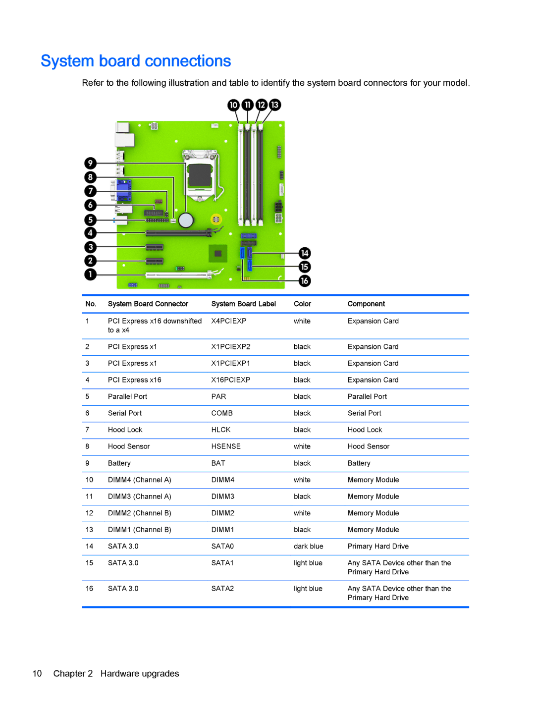
Refer to the following illustration and table to identify the system board connectors for your model.
No. | System Board Connector | System Board Label | Color | Component |
|
|
|
|
|
1 | PCI Express x16 downshifted | X4PCIEXP | white | Expansion Card |
| to a x4 |
|
|
|
|
|
|
|
|
2 | PCI Express x1 | X1PCIEXP2 | black | Expansion Card |
|
|
|
|
|
3 | PCI Express x1 | X1PCIEXP1 | black | Expansion Card |
|
|
|
|
|
4 | PCI Express x16 | X16PCIEXP | black | Expansion Card |
|
|
|
|
|
5 | Parallel Port | PAR | black | Parallel Port |
|
|
|
|
|
6 | Serial Port | COMB | black | Serial Port |
|
|
|
|
|
7 | Hood Lock | HLCK | black | Hood Lock |
|
|
|
|
|
8 | Hood Sensor | HSENSE | white | Hood Sensor |
|
|
|
|
|
9 | Battery | BAT | black | Battery |
|
|
|
|
|
10 | DIMM4 (Channel A) | DIMM4 | white | Memory Module |
|
|
|
|
|
11 | DIMM3 (Channel A) | DIMM3 | black | Memory Module |
|
|
|
|
|
12 | DIMM2 (Channel B) | DIMM2 | white | Memory Module |
|
|
|
|
|
13 | DIMM1 (Channel B) | DIMM1 | black | Memory Module |
|
|
|
|
|
14 | SATA 3.0 | SATA0 | dark blue | Primary Hard Drive |
|
|
|
|
|
15 | SATA 3.0 | SATA1 | light blue | Any SATA Device other than the |
|
|
|
| Primary Hard Drive |
|
|
|
|
|
16 | SATA 3.0 | SATA2 | light blue | Any SATA Device other than the |
|
|
|
| Primary Hard Drive |
|
|
|
|
|
10 Chapter 2 Hardware upgrades