Manuals
/
HP
/
Computer Equipment
/
Tablet
HP
7 Plus G2 - 1331 Removal and replacement procedures, Tablet component replacement procedures
Models:
7 Plus G2 - 1331
1
18
37
37
Download
37 pages
1.07 Kb
15
16
17
18
19
20
21
22
Specification
Wireless networking
Cables and connectors
Battery
Volume control buttons
Safety
Power cord set requirements
Page 18
Image 18
Page 17
Page 19
Page 18
Image 18
Page 17
Page 19
Contents
HP 7 Plus G2 Tablet
Product notice
Software terms
Safety warning notice
iv Safety warning notice
Table of contents
Power cord set requirements
Requirements for all countries
Requirements for specific countries and regions
Recycling
Power requirements
1 Product description
Wireless networking
Serviceability
Component
2 External component identification
Power button
Rear-facing webcam
Audio-out headphone/Audio-in
Volume control buttons
Micro USB 2.0 port
Micro SD Card Reader slot
3 Illustrated parts catalog
Locating the product number and serial number
Spare part number
Tablet major components
Tablet major components
Audio jack light pipe
5-V / 1-A AC adapter
Miscellaneous parts
Sequential part number listing
Cable Kit
Sequential part number listing
Cables and connectors
4 Removal and replacement preliminary requirements
Service considerations
Tools required
Grounding guidelines
Electrostatic discharge damage
Workstation guidelines
Packaging and transporting guidelines
Equipment guidelines
Material
Voltage protection level
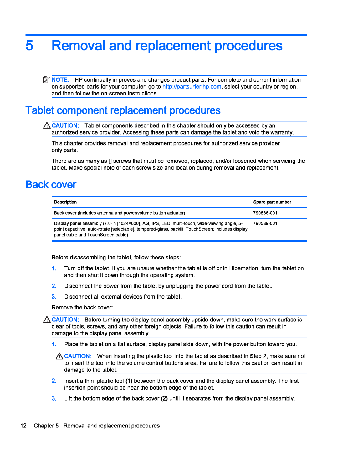
5 Removal and replacement procedures
Tablet component replacement procedures
Back cover
4. Remove the back cover
The actuators are included in the back cover spare part kit
Back cover
Battery
5. Remove the battery Reverse this procedure to install the battery
Battery
Antenna
Spare part number
Speaker
4. Remove the speaker Reverse this procedure to install the speaker
18 Chapter 5 Removal and replacement procedures
Rear-facing webcam
Microphone
Connector board
System board
4 XRay cable ZIF connector on system board
1 Connector board cable see Connector board on page
3 TouchScreen cable ZIF connector on system board
5 Power/volume button board cable ZIF connector on system board
Front-facing webcam
Front-facing webcam
Metric
6 Specifications
Input power
19.3 cm
7 Power cord set requirements
Requirements for all countries
Requirements for specific countries and regions
28 Chapter 7 Power cord set requirements
8 Recycling
Index
J jacks
T tablet
Top
Page
Image
Contents