8100 specifications
The HP 8100 series is a line of powerful and versatile printers designed to meet the demanding needs of businesses and offices. Known for its durability and efficiency, the HP 8100 is particularly popular among professionals seeking high-quality prints with fast turnaround times.One of the standout features of the HP 8100 is its capability to deliver impressive print speeds. With a print speed of up to 60 pages per minute, this printer significantly reduces wait times, allowing businesses to increase productivity. Furthermore, the first page out time is remarkably fast, making it ideal for busy office environments requiring quick document retrieval.
The HP 8100 utilizes HP's advanced LaserJet technology, which ensures sharp and consistent print quality across a range of media types. The printer is capable of producing professional-grade documents with a resolution of up to 1200 x 1200 dpi, making text crisp and images vibrant. This high-quality output is essential for creating marketing materials, reports, and other important documentation.
Another significant characteristic of the HP 8100 is its expandable paper handling capabilities. The printer comes with a standard input tray that accommodates a substantial volume of paper, while optional trays can be added to further increase capacity. This flexibility is particularly beneficial for businesses managing high-volume printing tasks.
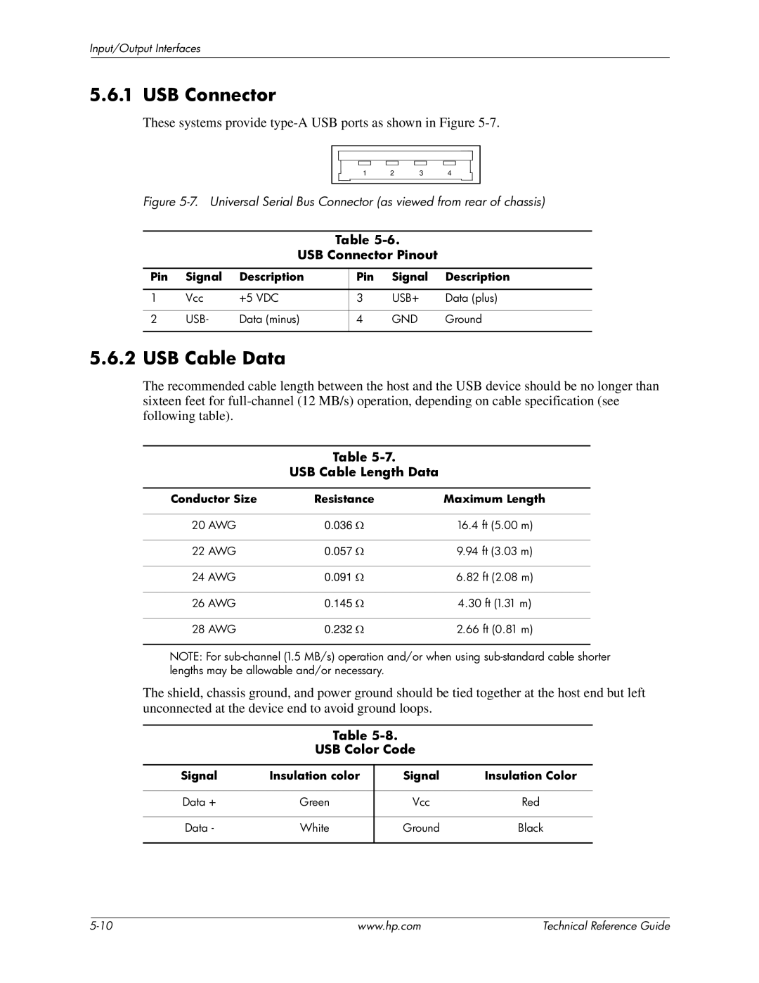
The HP 8100 is equipped with a variety of connectivity options, including USB, Ethernet, and wireless capabilities. This versatility allows for easy integration with existing office networks, enabling multiple users to access the printer simultaneously. Additionally, mobile printing features support printing from smartphones and tablets, enhancing convenience for on-the-go professionals.
Energy efficiency is another major advantage of the HP 8100 series. Designed to consume less energy, this printer adheres to energy-saving standards, which can help reduce operational costs for businesses. The printer’s efficiency is complemented by its reliable performance, often with minimal maintenance requirements, ensuring that it remains a staple in the office for years to come.
In the realm of security, HP provides several features to protect sensitive information. Secure printing options and user authentication help safeguard documents, which is crucial for maintaining confidentiality in corporate environments.
Overall, the HP 8100 series stands out for its exceptional print speed, high-quality output, robust connectivity options, and energy efficiency. These characteristics make it an excellent choice for businesses looking to enhance their printing capabilities.

