8200 tower specifications
The HP 8200 Tower is a robust desktop computer designed for professional environments, delivering performance and expandability for a variety of business needs. This workstation is part of HP's Elite series, known for its reliability and advanced technologies, making it a sound choice for companies requiring consistent operation.One of the defining features of the HP 8200 Tower is its versatile processing power, powered by the Intel Core i5 and i7 processors. These processors offer a multi-core architecture, ensuring that users can efficiently handle multitasking and processor-intensive applications. With options for up to 32GB of DDR3 RAM, the HP 8200 Tower can smoothly run multiple applications simultaneously, making it suitable for tasks ranging from everyday office work to more demanding software like graphical design programs.
The system also provides a range of storage options, including traditional hard disk drives and faster solid-state drives, allowing users to select the balance of capacity and speed that best suits their needs. Additionally, the HP 8200 supports RAID configurations, enhancing data redundancy and performance, thereby protecting critical business data.
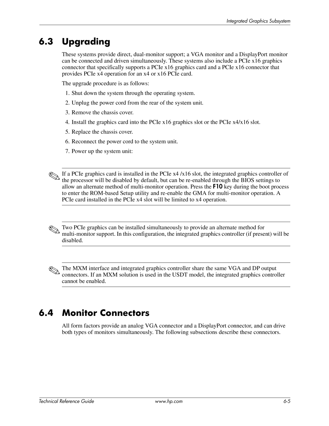
In terms of expandability, the HP 8200 Tower offers multiple PCIe slots for adding graphic cards, sound cards, or other expansion cards. This capability makes it adaptable for various purposes, whether that involves improving graphics performance for video editing or integrating specialized hardware for specific business functions.
The design of the HP 8200 Tower ensures efficient cooling and quiet operation. It features a tool-less chassis, allowing for easy upgrades and maintenance. The internal layout maximizes airflow, keeping components cool even under heavy workloads, an important feature for maintaining long-lasting performance.
Connectivity options are plentiful, with USB 2.0 and USB 3.0 ports, enabling speedy data transfer and peripheral connectivity. Additionally, integrated Gigabit Ethernet offers reliable networking capabilities, essential for seamless communication within a business environment.
The HP 8200 Tower showcases HP's commitment to sustainability, featuring energy-efficient components and a design aimed at reducing environmental impact. Overall, this powerful workstation combines performance, expandability, and energy efficiency, making it an excellent choice for any professional setting. With its blend of modern technologies and traditional reliability, the HP 8200 Tower stands out as a dependable tool for businesses looking to enhance productivity.

