Power and Signal Distribution

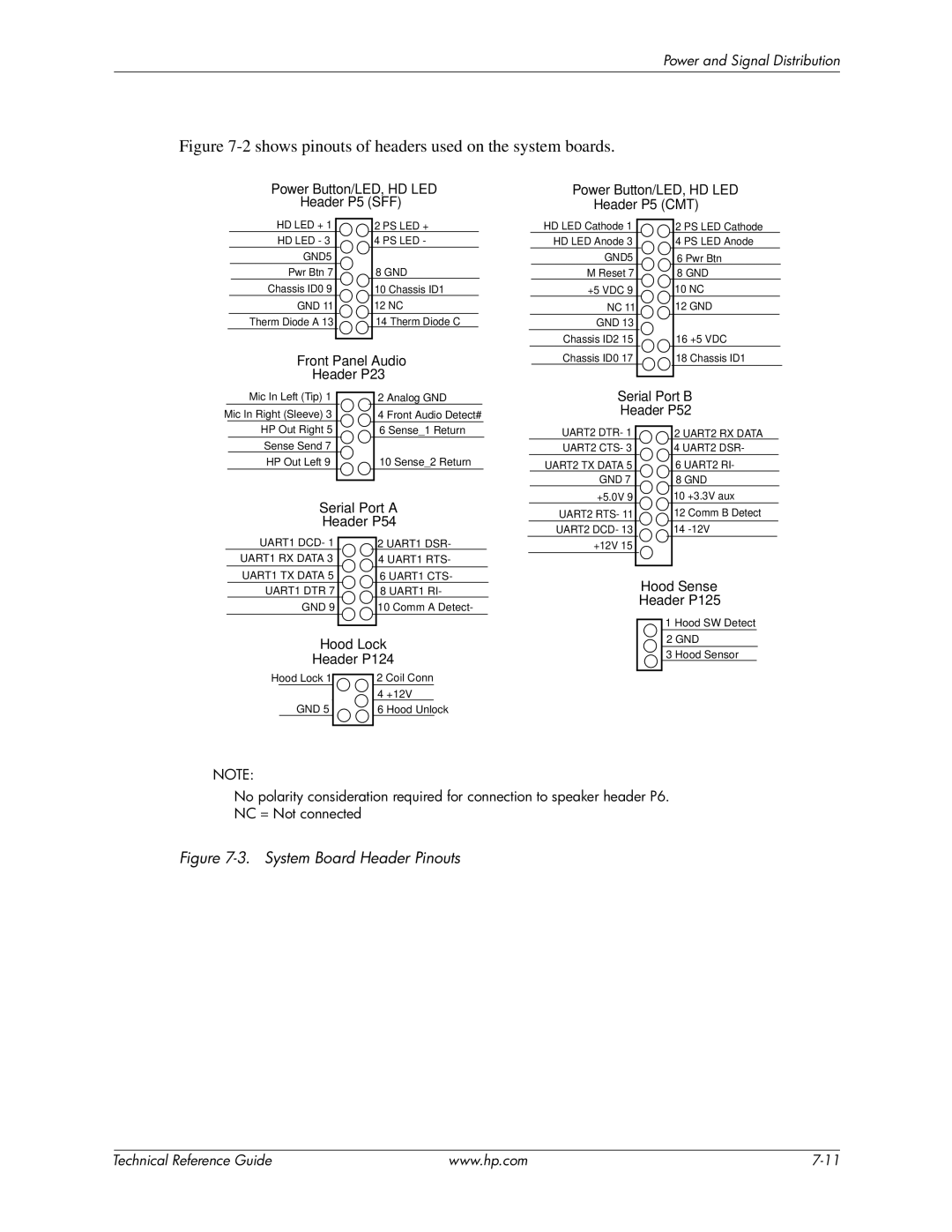
Figure 7-2 shows pinouts of headers used on the system boards.

Power Button/LED, HD LED

Power Button/LED, HD LED

Header P5 (SFF)

Header P5 (CMT)

HD LED + 1

HD LED - 3

GND5

Pwr Btn 7

Chassis ID0 9

GND 11

Therm Diode A 13

2 PS LED +

4 PS LED -

8 GND

10 Chassis ID1

12 NC

14 Therm Diode C

HD LED Cathode 1

HD LED Anode 3

GND5

M Reset 7

+5 VDC 9

NC 11

GND 13

Chassis ID2 15

2 PS LED Cathode

4 PS LED Anode

6 Pwr Btn

8GND 10 NC 12 GND

16 +5 VDC

Front Panel Audio

Chassis ID0 17

Header P23


18 Chassis ID1


Mic In Left (Tip) 1


2 Analog GND


Serial Port B


Header P52


Mic In Right (Sleeve) 3


4 Front Audio Detect#


HP Out Right 5


6 Sense_1 Return


UART2 DTR- 1


2 UART2 RX DATA


Sense Send 7


UART2 CTS- 3


4 UART2 DSR-


HP Out Left 9


10 Sense_2 Return


UART2 TX DATA 5


6 UART2 RI-


GND 7


8 GND


Serial Port A


+5.0V 9


10 +3.3V aux


UART2 RTS- 11


12 Comm B Detect


Header P54


UART2 DCD- 13


14 -12V


UART1 DCD- 1


2 UART1 DSR-


+12V 15


UART1 RX DATA 3


4 UART1 RTS-


UART1 TX DATA 5


6 UART1 CTS-


Hood Sense


UART1 DTR 7


8 UART1 RI-


GND 9


10 Comm A Detect-


Header P125


1 Hood SW Detect


Hood Lock


2 GND


3 Hood Sensor


Header P124


Hood Lock 1


2 Coil Conn


4 +12V


GND 5


6 Hood Unlock


NOTE:

No polarity consideration required for connection to speaker header P6. NC = Not connected

Figure 7-3. System Board Header Pinouts

Technical Reference Guide

www.hp.com

7-11

Page 83
Image 83
HP 8200 tower manual Shows pinouts of headers used on the system boards

8200 tower specifications

The HP 8200 Tower is a robust desktop computer designed for professional environments, delivering performance and expandability for a variety of business needs. This workstation is part of HP's Elite series, known for its reliability and advanced technologies, making it a sound choice for companies requiring consistent operation.

One of the defining features of the HP 8200 Tower is its versatile processing power, powered by the Intel Core i5 and i7 processors. These processors offer a multi-core architecture, ensuring that users can efficiently handle multitasking and processor-intensive applications. With options for up to 32GB of DDR3 RAM, the HP 8200 Tower can smoothly run multiple applications simultaneously, making it suitable for tasks ranging from everyday office work to more demanding software like graphical design programs.

The system also provides a range of storage options, including traditional hard disk drives and faster solid-state drives, allowing users to select the balance of capacity and speed that best suits their needs. Additionally, the HP 8200 supports RAID configurations, enhancing data redundancy and performance, thereby protecting critical business data.

In terms of expandability, the HP 8200 Tower offers multiple PCIe slots for adding graphic cards, sound cards, or other expansion cards. This capability makes it adaptable for various purposes, whether that involves improving graphics performance for video editing or integrating specialized hardware for specific business functions.

The design of the HP 8200 Tower ensures efficient cooling and quiet operation. It features a tool-less chassis, allowing for easy upgrades and maintenance. The internal layout maximizes airflow, keeping components cool even under heavy workloads, an important feature for maintaining long-lasting performance.

Connectivity options are plentiful, with USB 2.0 and USB 3.0 ports, enabling speedy data transfer and peripheral connectivity. Additionally, integrated Gigabit Ethernet offers reliable networking capabilities, essential for seamless communication within a business environment.

The HP 8200 Tower showcases HP's commitment to sustainability, featuring energy-efficient components and a design aimed at reducing environmental impact. Overall, this powerful workstation combines performance, expandability, and energy efficiency, making it an excellent choice for any professional setting. With its blend of modern technologies and traditional reliability, the HP 8200 Tower stands out as a dependable tool for businesses looking to enhance productivity.