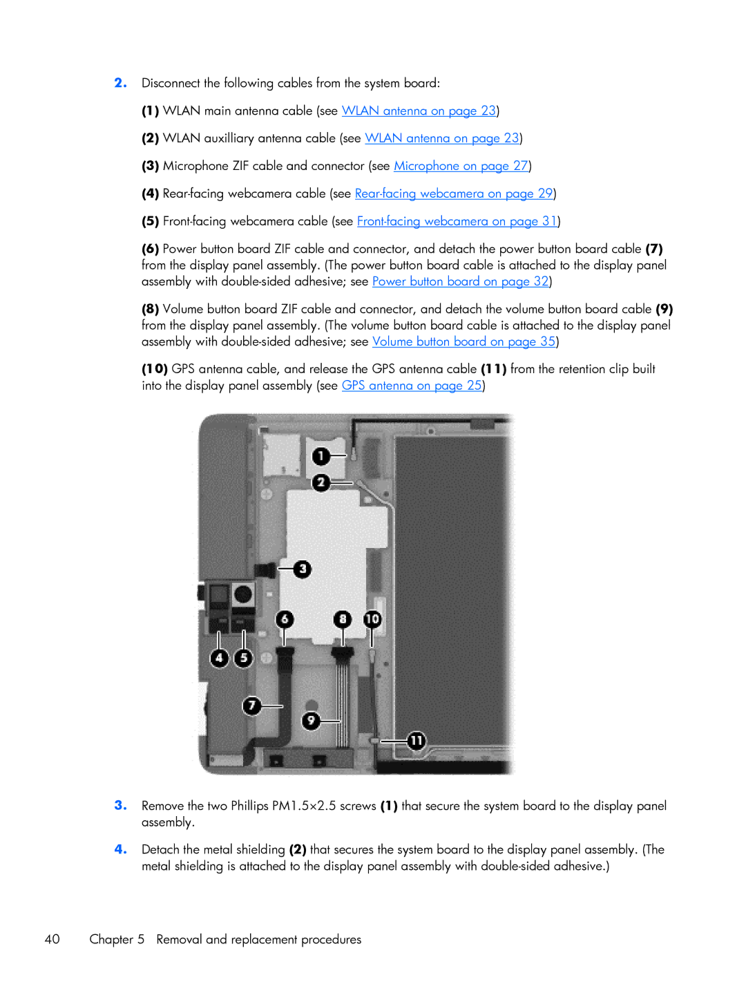
2.Disconnect the following cables from the system board:
(1)WLAN main antenna cable (see WLAN antenna on page 23)
(2)WLAN auxilliary antenna cable (see WLAN antenna on page 23)
(3)Microphone ZIF cable and connector (see Microphone on page 27)
(4)
(5)
(6)Power button board ZIF cable and connector, and detach the power button board cable (7) from the display panel assembly. (The power button board cable is attached to the display panel assembly with
(8)Volume button board ZIF cable and connector, and detach the volume button board cable (9) from the display panel assembly. (The volume button board cable is attached to the display panel assembly with
(10)GPS antenna cable, and release the GPS antenna cable (11) from the retention clip built into the display panel assembly (see GPS antenna on page 25)
3.Remove the two Phillips PM1.5×2.5 screws (1) that secure the system board to the display panel assembly.
4.Detach the metal shielding (2) that secures the system board to the display panel assembly. (The metal shielding is attached to the display panel assembly with
40 | Chapter 5 Removal and replacement procedures |