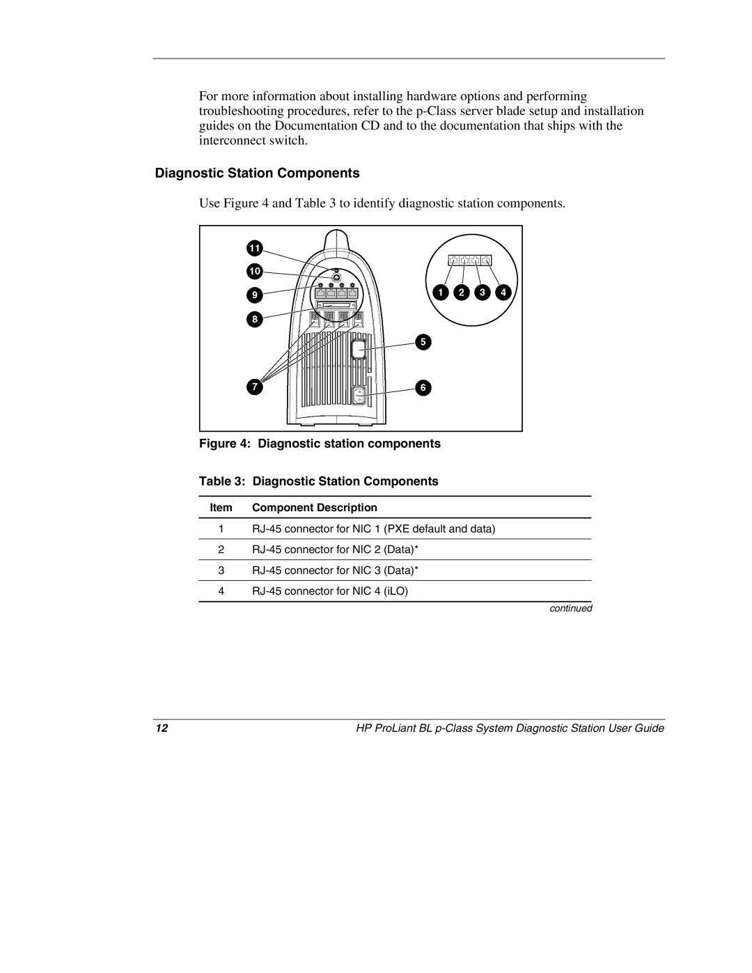
BL p-Class System 230859-004 specifications
The HP BL p-Class System 230859-004 is a powerful blade server designed to meet the demanding needs of enterprise IT environments. As part of HP's renowned BladeSystem line, this system is engineered for flexibility, scalability, and manageability in a compact form factor, allowing organizations to maximize their data center's efficiency.One of the standout features of the HP BL p-Class System is its modular architecture. The system allows for multiple blade servers to be housed within a single enclosure, which saves valuable space and reduces power consumption. The 230859-004 model supports various blade types, offering the ability to mix and match different servers and configurations based on specific workload requirements.
In terms of processing power, the system is equipped with high-performance Intel Xeon processors. These processors provide significant computational power, enabling the execution of demanding applications while ensuring reliable performance. This capability is essential for organizations that require efficient handling of heavy workloads, such as virtualization and data analytics.
Memory expansion is another noteworthy characteristic of the HP BL p-Class System. The system supports a substantial amount of RAM, allowing for increased multitasking and enhanced application performance. This memory scalability is critical for maintaining responsiveness in enterprise applications while also facilitating the running of virtual machines.
HP's innovative technologies also elevate the capabilities of the BL p-Class System 230859-004. The system integrates HP Insight Management tools, which simplify the monitoring and management of the blade servers. This management suite helps IT administrators streamline their operations, reduce downtime, and ensure that systems are running optimally.
Moreover, the blade system leverages HP's Virtual Connect technology, which provides flexible networking options. This technology allows for easy connection and management of network resources, enabling organizations to quickly adapt to changing business needs without extensive reconfiguration.
The HP BL p-Class System 230859-004 is also designed with advanced cooling solutions. The blade enclosure is built to optimize airflow and maintain optimal thermal conditions, which is vital for longevity and reliability in high-density environments.
Overall, the HP BL p-Class System 230859-004 is a robust solution that combines powerful processing capabilities, memory scalability, and innovative management technologies. Its design emphasizes efficiency and adaptability, making it a suitable choice for organizations looking to enhance their data center infrastructure. With these features, the system stands out as a valuable asset for meeting the evolving demands of enterprise computing.

