Enabling dynamic power saver
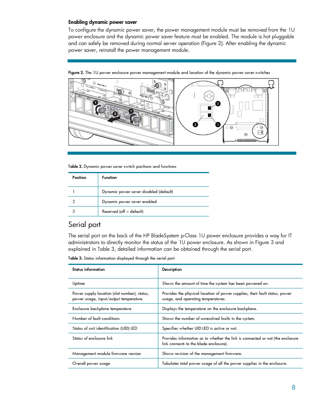
To configure the dynamic power saver, the power management module must be removed from the 1U power enclosure and the dynamic power saver feature must be enabled. The module is hot pluggable and can safely be removed during normal server operation (Figure 2). After enabling the dynamic power saver, reinstall the power management module.
Figure 2. The 1U power enclosure power management module and location of the dynamic power saver switches
Table 2. Dynamic power saver switch positions and functions
Position Function
1Dynamic power saver disabled (default)
2Dynamic power saver enabled
3Reserved (off = default)
Serial port
The serial port on the back of the HP BladeSystem
Table 3. Status information displayed through the serial port
Status information | Description |
|
|
Uptime | Shows the amount of time the system has been powered on. |
|
|
Power supply location (slot number), status, | Provides the physical location of power supplies, their fault status, power |
power usage, input/output temperature | usage, and operating temperatures. |
|
|
Enclosure backplane temperature | Displays the temperature on the enclosure backplane. |
|
|
Number of fault conditions | Shows the number of unresolved faults in the system. |
|
|
Status of unit identification (UID) LED | Specifies whether UID LED is active or not. |
|
|
Status of enclosure link | Provides information as to whether the link is connected or not (the enclosure |
| link connects to the blade enclosure). |
|
|
Management module firmware version | Shows revision of the management firmware. |
|
|
Overall power usage | Tabulates total power usage of all the power supplies in the enclosure. |
|
|
8