Front Panel Components
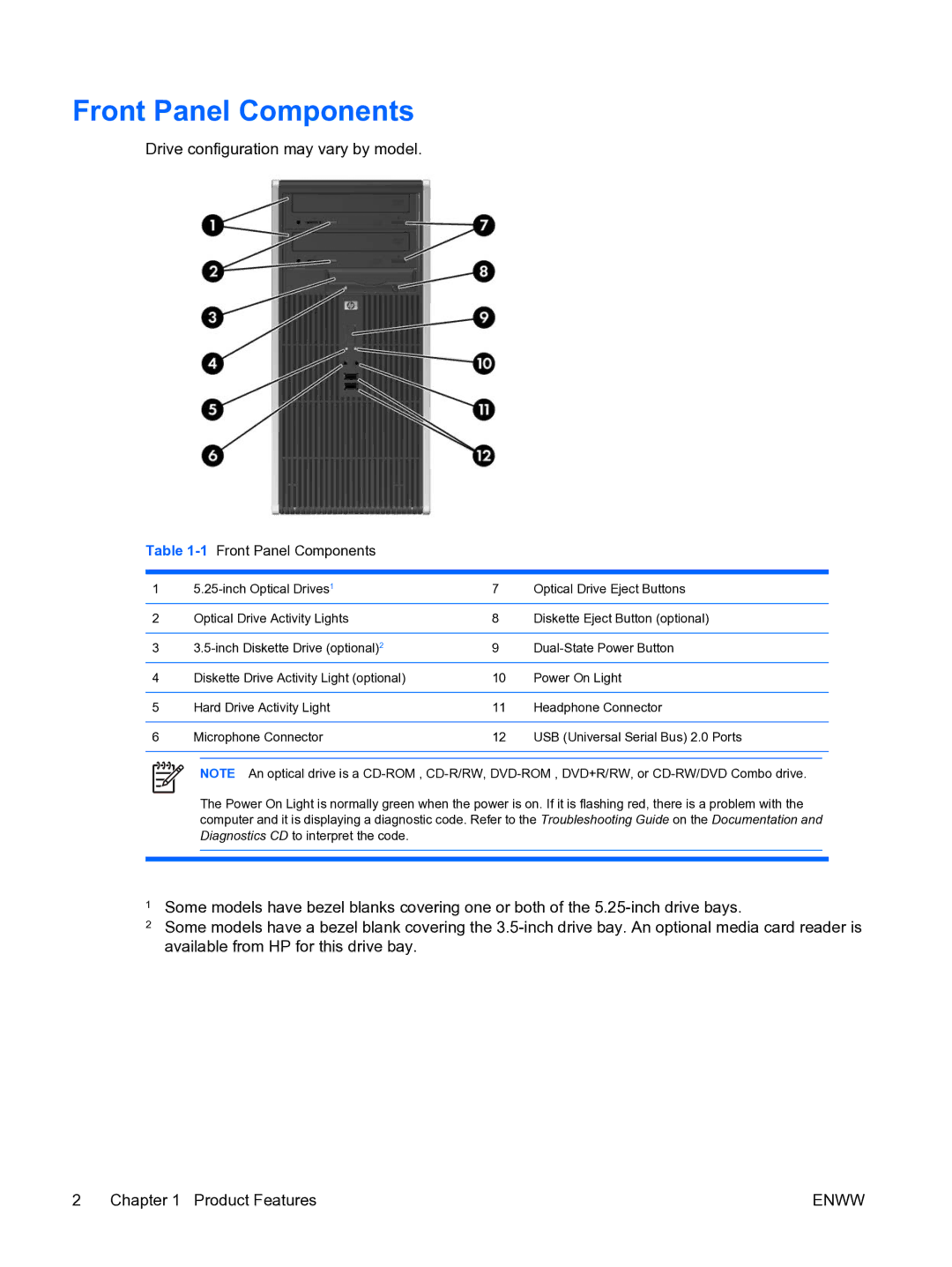
Drive configuration may vary by model.
Table 1-1 Front Panel Components
1 | 7 | Optical Drive Eject Buttons | |||
|
|
|
|
|
|
2 | Optical Drive Activity Lights | 8 | Diskette Eject Button (optional) | ||
|
|
|
|
|
|
3 | 9 | ||||
|
|
|
|
|
|
4 | Diskette Drive Activity Light (optional) | 10 | Power On Light | ||
|
|
|
|
|
|
5 | Hard Drive Activity Light | 11 | Headphone Connector | ||
|
|
|
|
|
|
6 | Microphone Connector | 12 | USB (Universal Serial Bus) 2.0 Ports | ||
|
|
|
|
|
|
|
|
|
|
|
|
NOTE An optical drive is a
The Power On Light is normally green when the power is on. If it is flashing red, there is a problem with the computer and it is displaying a diagnostic code. Refer to the Troubleshooting Guide on the Documentation and Diagnostics CD to interpret the code.
1Some models have bezel blanks covering one or both of the
2Some models have a bezel blank covering the
2 Chapter 1 Product Features | ENWW |