Step 4. Record the Product Identification
Information
Installing the HP-PCI ATM/622 Adapter
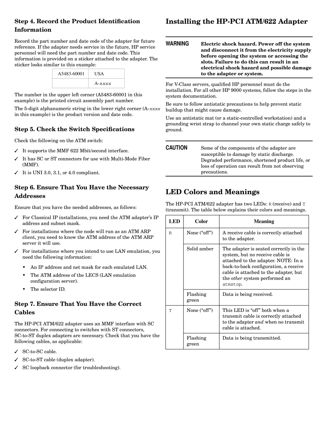
Record the part number and date code of the adapter for future reference. If the adapter needs service in the future, HP service personnel will need the part number and date code. This information is provided on a sticker attached to the adapter. The sticker looks similar to this example:
USA | |
|
|
| |
|
|
The number in the upper left corner
The
Step 5. Check the Switch Specifications
Check the following on the ATM switch:
✓It supports the MMF 622 Mbit/second interface.
✓It has SC or ST connectors for use with
✓It is UNI 3.0, 3.1, or 4.0 compliant.
WARNING Electric shock hazard. Power off the system and disconnect it from the electricity supply before opening the system or accessing the slots. Failure to do this can result in an electrical shock hazard and possible damage to the adapter or system.
For
Be sure to follow antistatic precautions to help prevent static buildup that might cause damage.
Use an antistatic mat (or a
CAUTION Some of the components of the adapter are susceptible to damage by static discharge. Degraded performance, shortened product life, or loss of operation can result from not observing precautions.
Step 6. Ensure That You Have the Necessary
Addresses
Ensure that you have the needed addresses, as follows:
✓For Classical IP installations, you need the ATM adapter’s IP address and subnet mask.
✓For installations where the node will run as an ATM ARP client, you need to know the ATM address of the ATM ARP server it will use.
✓For installations where you intend to use LAN emulation, you need the following information:
•An IP address and net mask for each emulated LAN.
•The ATM address of the LECS (LAN emulation configuration server).
•The selector ID.
Step 7. Ensure That You Have the Correct
Cables
The
✓
✓
✓SC loopback connector (for troubleshooting).
LED Colors and Meanings
The
LED | Color | Meaning |
|
|
|
R | None (“off”) | A receive cable is correctly attached |
|
| to the adapter. |
|
|
|
| Solid amber | The adapter is seated correctly in the |
|
| system, but no receive cable is |
|
| attached to the adapter. NOTE: In a |
|
| |
|
| cable is attached to the adapter, but |
|
| the other system performed an |
|
| atmstop. |
|
|
|
| Flashing | Data is being received. |
| green |
|
|
|
|
T | None (“off”) | This LED is “off” both when a |
|
| transmit cable is correctly attached |
|
| to the adapter and when no transmit |
|
| cable is attached. |
|
|
|
| Flashing | Data is being transmitted. |
| green |
|
|
|
|