ASSEMBLY
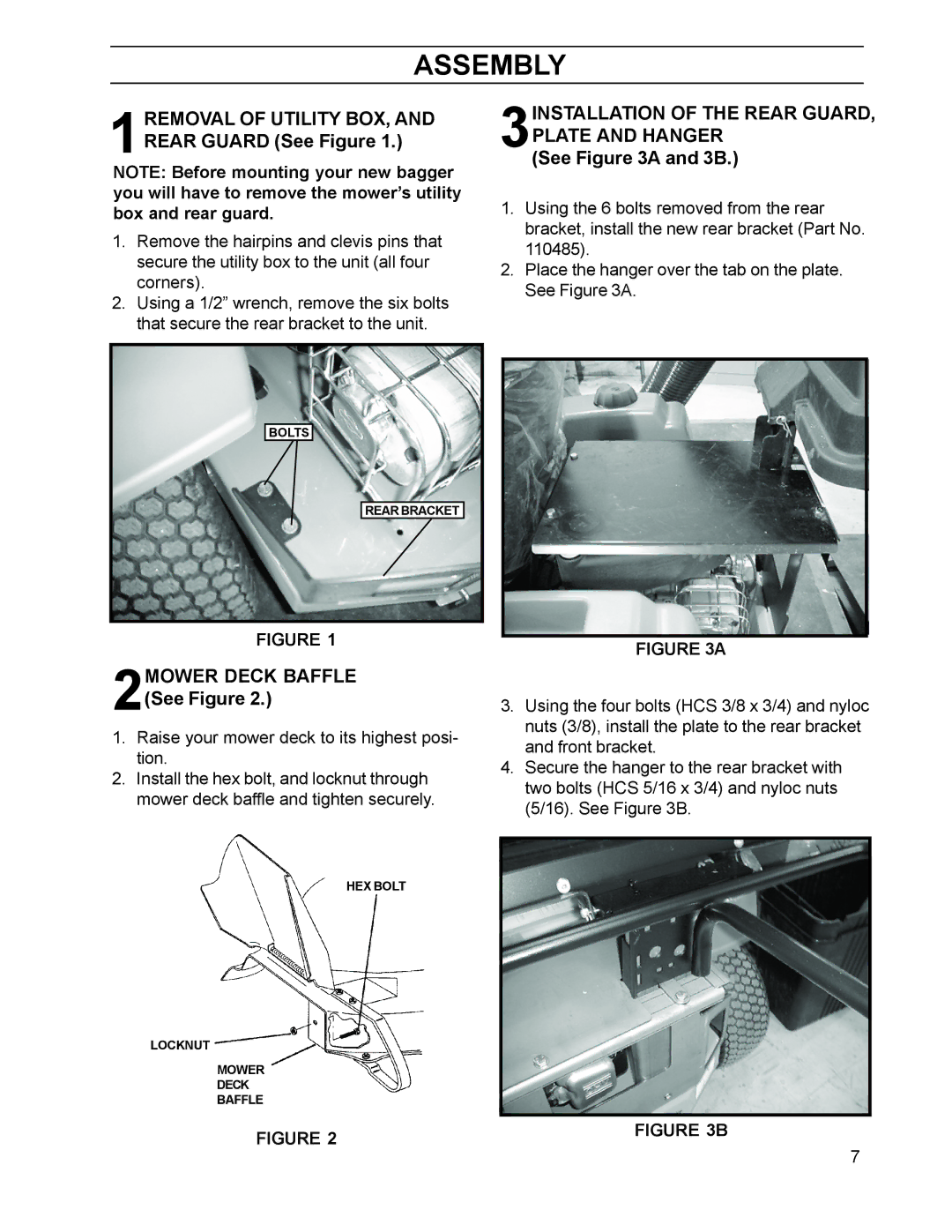
1REMOVAL OF UTILITY BOX, AND REAR GUARD (See Figure 1.)
NOTE: Before mounting your new bagger you will have to remove the mower’s utility box and rear guard.
1.Remove the hairpins and clevis pins that secure the utility box to the unit (all four corners).
2.Using a 1/2” wrench, remove the six bolts that secure the rear bracket to the unit.
BOLTS
REAR BRACKET
FIGURE 1
2MOWER DECK BAFFLE (See Figure 2.)
1.Raise your mower deck to its highest posi- tion.
2.Install the hex bolt, and locknut through mower deck baffle and tighten securely.
HEX BOLT
LOCKNUT
MOWER
DECK
BAFFLE
FIGURE 2
3INSTALLATION OF THE REAR GUARD,
PLATE AND HANGER
(See Figure 3A and 3B.)
1.Using the 6 bolts removed from the rear bracket, install the new rear bracket (Part No. 110485).
2.Place the hanger over the tab on the plate. See Figure 3A.
FIGURE 3A
3.Using the four bolts (HCS 3/8 x 3/4) and nyloc nuts (3/8), install the plate to the rear bracket and front bracket.
4.Secure the hanger to the rear bracket with two bolts (HCS 5/16 x 3/4) and nyloc nuts (5/16). See Figure 3B.
FIGURE 3B
7