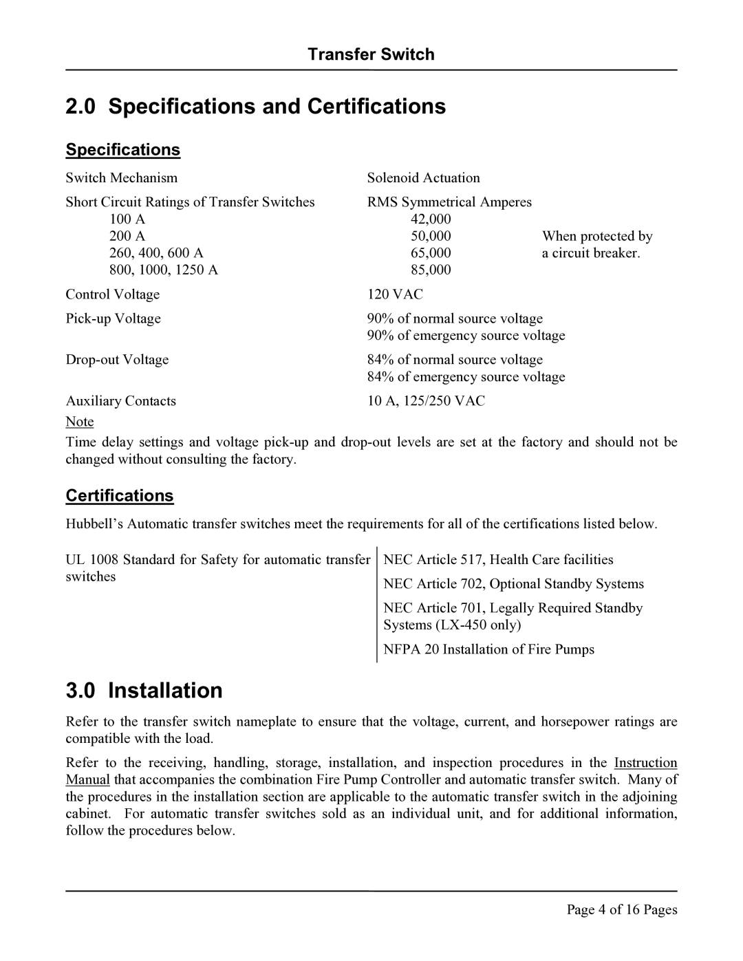
LX-450, LX-440 specifications
The Hubbell LX-440 and LX-450 are cutting-edge LED lighting solutions designed to meet the demands of various commercial and industrial applications. These products stand out for their exceptional energy efficiency, durability, and advanced technology, making them ideal for environments ranging from manufacturing facilities to retail spaces.One of the primary features of the LX-440 and LX-450 is their robust construction. Built to withstand harsh conditions, the fixtures are engineered with high-quality materials that ensure longevity and reduced maintenance costs. The body of both models is designed to resist corrosion, making them suitable for use in environments exposed to moisture and chemicals. This makes the LX series particularly appealing for industries such as food processing, pharmaceuticals, and chemical manufacturing.
In terms of technology, the LX-440 and LX-450 utilize state-of-the-art LED technology to provide high lumen output with minimal energy consumption. This translates to substantial savings on energy bills and a reduced carbon footprint. With options for various color temperatures, users can select the lighting that best enhances visibility and comfort in their specific environments. These fixtures also boast an impressive lifespan of up to 100,000 hours, significantly reducing the need for frequent replacements.
Another significant characteristic of these models is their versatile installation options. The LX-440 and LX-450 can be easily mounted in a variety of settings, including pendant, surface, or chain mounting. This flexibility allows for customized layouts that can adapt to changing needs or configurations of the space. Furthermore, they feature a sleek and unobtrusive design that blends well with any decor, making them suitable for both industrial and commercial applications.
The LX series also includes advanced features such as integrated sensors for occupancy and daylight harvesting, which further enhance energy savings by ensuring that lights are on only when needed. These intelligent lighting solutions respond to their environment, adjusting brightness levels automatically to maintain optimal lighting conditions while minimizing energy use.
In summary, the Hubbell LX-440 and LX-450 represent the pinnacle of modern lighting technology. With their durable construction, advanced LED efficiency, customizable installation options, and smart features, these fixtures are ideal choices for businesses looking to improve their lighting solutions while achieving significant energy savings.

