INSTALLATION and MAINTENANCE INSTRUCTIONS
TMR SERIES ELECTRIC CABLE REELS
DESCRIPTION
The TMR series reel is designed to automatically lift and retrieve electric cable. The reel incorporates a rotating hollow shaft with spool mounted outboard on one end and collector assembly on the opposite end. The main shaft, rotating on two flange block bearings, is driven by an electric torque motor through a chain drive. The torque motor has an electronically released break holding the spool stationary when the reel is not in use.
INSTALLATION
1.Thoroughly inspect reel upon receipt for damage that may have been caused in shipping.
2.Mount reel with the main shaft horizontal and level and with the spool centerline in line with the cable tray. Mount at recommended height so that proper distance from the center of the spool to the cable tray is maintained.
CAUTION
Exceeding designed lift distance may lead
to poor cable spooling and
erratic operation because the electric motor
will have insufficient torque.
3.Remove collector cover. Connect conduit to line entrance of collector housing and connect wires to brushes of collector assembly. Brush terminals are number coded. Be careful that incoming wires do not put strain on brush terminals and cause brush misalignment. Replace collector cover.
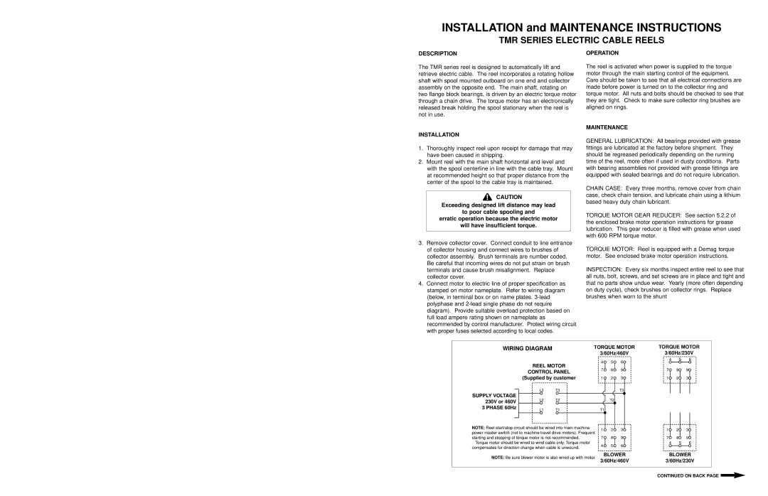
4.Connect motor to electric line of proper specification as stamped on motor nameplate. Refer to wiring diagram (below, in terminal box or on name plates.
OPERATION
The reel is activated when power is supplied to the torque motor through the main starting control of the equipment. Care should be taken to see that all electrical connections are made before power is turned on to the collector ring and torque motor. All nuts and bolts should be checked to see that they are tight. Check to make sure collector ring brushes are aligned on rings.
MAINTENANCE
GENERAL LUBRICATION: All bearings provided with grease fittings are lubricated at the factory before shipment. They should be regreased periodically depending on the running time of the reel, more often if used in dusty conditions. Parts with bearing assemblies not provided with grease fittings are equipped with sealed bearings and do not require lubrication.
CHAIN CASE: Every three months, remove cover from chain case, check chain tension, and lubricate chain using a lithium based heavy duty chain lubricant.
TORQUE MOTOR GEAR REDUCER: See section 5.2.2 of the enclosed brake motor operation instructions for grease lubrication. This gear reducer is filled with grease when used with 600 RPM torque motor.
TORQUE MOTOR: Reel is equipped with a Demag torque motor. See enclosed brake motor operation instructions.
INSPECTION: Every six months inspect entire reel to see that all nuts, bolt, screws, and set screws are in place and tight and that no parts show undue wear. Yearly (more often depending on duty cycle), check brushes on collector rings. Replace brushes when worn to the shunt
| TORQUE MOTOR | TORQUE MOTOR |
WIRING DIAGRAM | ||
| 3/60Hz/460V | 3/60Hz/230V |
REEL MOTOR
CONTROL PANEL
(Supplied by customer
| L3 | T3 | |
SUPPLY VOLTAGE | L2 | T2 | |
230V or 460V | |||
|
| ||
3 PHASE 60Hz | L1 | T1 | |
|
4 | 5 | 6 |
7 | 8 | 9 |
1 | 2 | 3 |
|
| T3 |
T2
T1
4 5 6
7 | 8 | 9 |
1 | 2 | 3 |
NOTE: Reel start/stop circuit should be wired into main machine power master switch (not to machine travel drive motors). Frequent starting and stopping of torque motor is not recommended.
Torque motor should be wired to wind cable only. Torque motor compensates for direction change when cable is unwound.
NOTE: Be sure blower motor is also wired up with motor.
1 | 2 | 3 |
7 | 8 | 9 |
4 | 5 | 6 |
BLOWER
3/60Hz/460V
1 | 2 | 3 |
7 | 8 | 9 |
4 5 6
BLOWER
3/60Hz/230V
CONTINUED ON BACK PAGE ![]()
