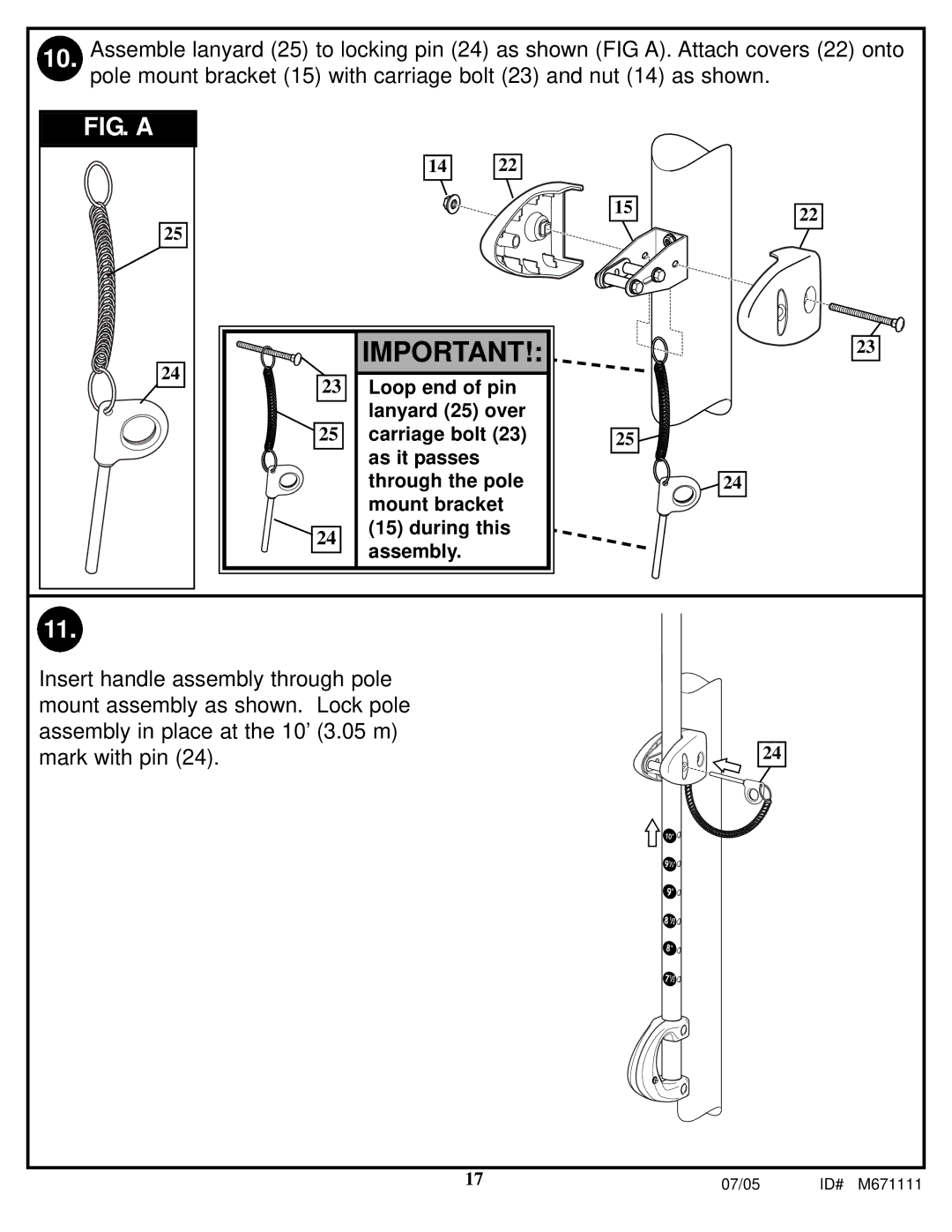
10. Assemble lanyard (25) to locking pin (24) as shown (FIG A). Attach covers (22) onto pole mount bracket (15) with carriage bolt (23) and nut (14) as shown.
FIG. A
25
24
14 | 22 |
|
|
|
|
|
|
|
|
|
|
|
|
|
| IMPORTANT!: |
| ||
|
| 23 |
|
|
| Loop end of pin |
|
|
|
|
|
|
|
| lanyard (25) over |
|
|
|
| 25 |
|
|
| carriage bolt (23) |
|
|
|
|
|
|
|
| as it passes |
|
|
|
|
|
|
|
|
|
| |
|
|
|
|
|
| through the pole |
|
|
|
|
|
|
|
| mount bracket |
|
|
|
|
|
|
|
| (15) during this |
|
|
|
| 24 |
|
|
|
|
| |
|
|
|
|
| assembly. |
|
| |
|
|
|
|
|
|
|
| |
|
|
|
|
|
|
|
|
|
|
|
|
|
|
|
|
|
|
15
25
![]()
![]()
![]()
![]() 24
24
22
23
11.
Insert handle assembly through pole mount assembly as shown. Lock pole assembly in place at the 10’ (3.05 m) mark with pin (24).
24
17 | 07/05 | ID# M671111 |
