27
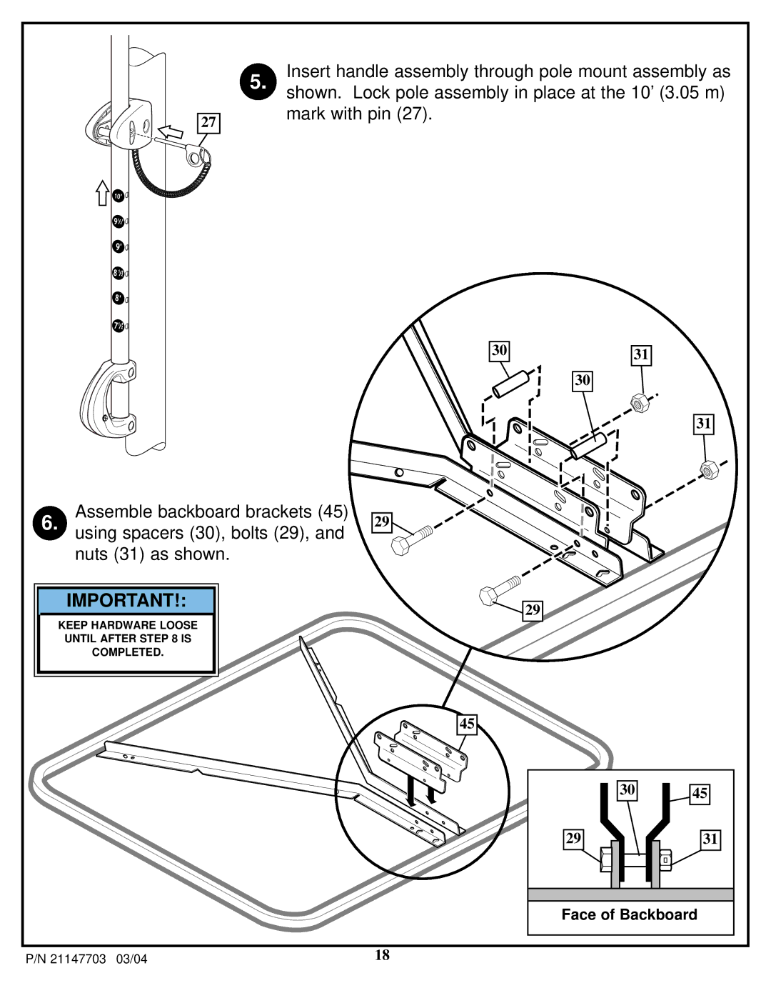
5. Insert handle assembly through pole mount assembly as shown. Lock pole assembly in place at the 10’ (3.05 m) mark with pin (27).
30
Assemble backboard brackets (45)
6. using spacers (30), bolts (29), and 29 nuts (31) as shown.
31
30
31
IMPORTANT!:
KEEP HARDWARE LOOSE UNTIL AFTER STEP 8 IS COMPLETED.
![]() 29
29
45
30
45
29
31
Face of Backboard
P/N 21147703 03/04 | 18 |
