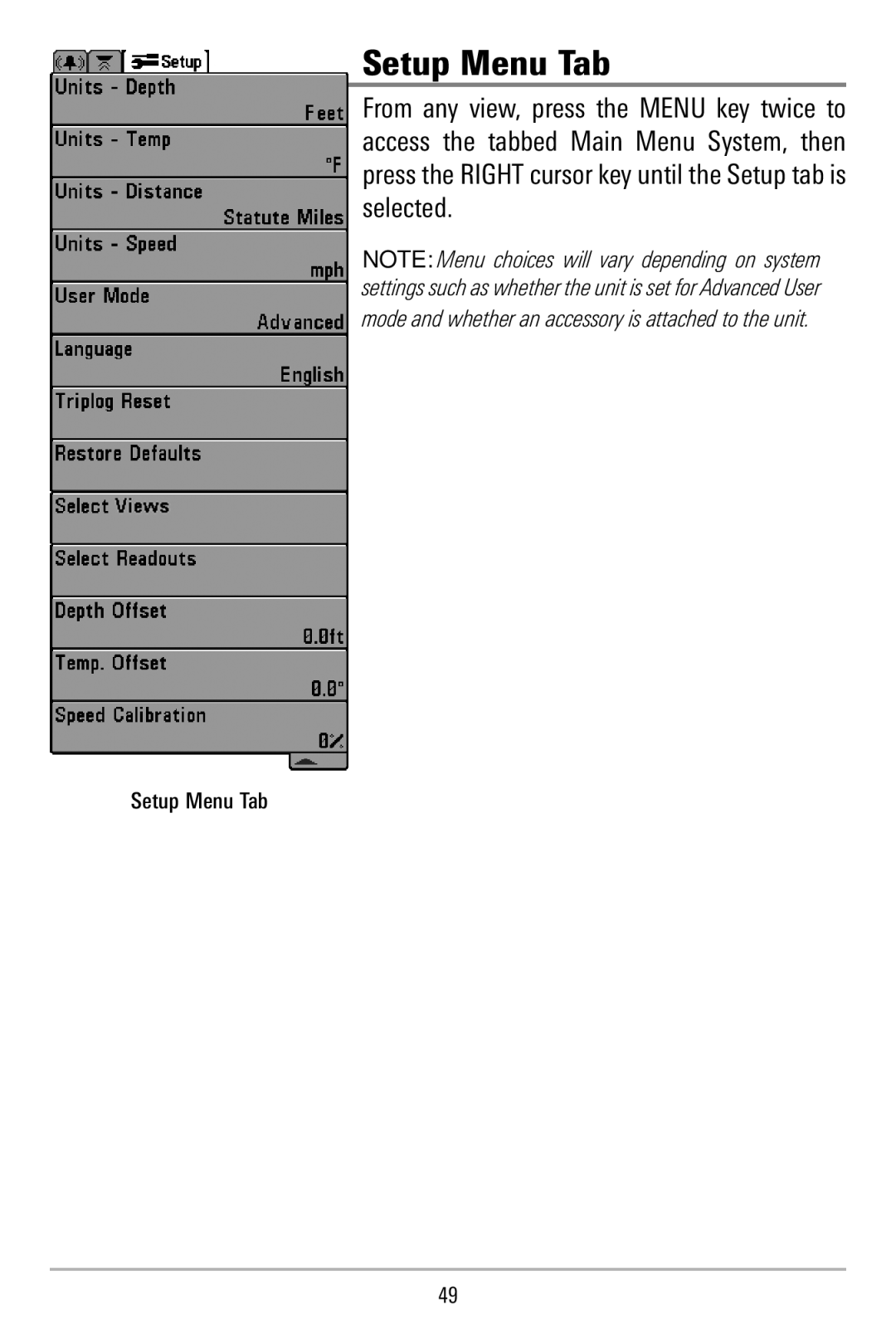
500 Series Operations Manual
531521-1A
Thank You
2006 Humminbird, Eufaula AL, USA. All rights reserved
How Sonar Works
Table of Contents
Powering Up the Unit
What’s On the Display
Sonar X-Press Menu
Alarms Menu Tab
Setup Menu Tab
Sonar Menu Tab
Specifications
Troubleshooting
500 Series Fishfinder Accessories
Glossary
How Sonar Works
Peak to Peak measures power output at the highest points
Single Beam Sonar
DualBeam Sonar
565 Fishfinders only
QuadraBeam PLUS Sonar
575 Fishfinders only
Distance - distance traveled with Temp/Speed Accessory
Temperature - water surface temperature
Timer - elapsed time with Temp/Speed Accessory
What’s On the Display
device is connected to the Fishfinder
Structure - where fish may be hiding
Soft Bottom RTS Real Time Sonar Window
200kHz,NarrowBeamShadedFishSymbol
Zoom View
Views
The views available on your Fishfinder are Sonar views Sonar View
Big Digits View Side Beam View 575 Fishfinder only
Sonar View
Sonar View
Understanding Sonar History
Real Time Sonar RTS Window
Bottom Presentation
Page
Page
Sonar Zoom View
Sonar Zoom View
200/83 kHz Split Sonar View
575 Fishfinders only
Big Digits View
575 Fishfinders only
Side Beam View
Depth Temperature Left Side 455 kHz Sonar History Window
200 kHz Sonar History Window Right Side 455 kHz Sonar History Window
Classic layout The top portion of the display presents a historical log of sonar returns from the 200 kHz down-looking sonar beam. The bottom portion of the display presents a historical log of sonar returns from the 455 kHz right- and left-looking sonar beams. New information appears at the top, and scrolls down the display
Slanted layout This layout presents the two 455 kHz side sonar beams and the 200 kHz down-looking sonar beam as three panels of historical data. This layout is presented as three slanted panels. New information appears on the right, and scrolls to the left
POWER/LIGHT Key
Key Functions
VIEW Key
MENU Key
4-WAY Cursor Control Key
EXIT Key
Powering Up the Unit
575 Title Screen
The Menu System
Sonar Tab Normal Mode Sonar Tab Advanced Mode
Normal Operation
Exit Normal operation by powering your Fishfinder off
Start-Up Options Menu
Normal Simulator System Status
Exit the Simulator by powering your Fishfinder off
Simulator
System Status
Self Test Accessory Test
Exit System Status by powering your Fishfinder off
Self Test
Accessory Test
Accessory Test lists the accessories connected to the system
Sonar X-Press Menu
Sonar X-Press Menu
NOTE Quad Layout only appears in Side Beam View on 575 Fishfinders
NOTE Zoom Level only appears in Sonar Zoom View
To adjust the Sensitivity
Sensitivity
1. Highlight Sensitivity on the Sonar X-Press menu
To adjust the Upper Range
Upper Range
Advanced Sonar, Split Sonar, Big Digits Views only
To adjust the Lower Range
Lower Range
1. Highlight Lower Range on the Sonar X-Press menu
Chart Speed
To adjust the Chart Speed
1. Highlight Chart Speed on the Sonar X-Press menu
Bottom View
Quad Layout
Zoom Level
Sonar Menu Tab
Sonar Menu
Beam Select
To use Beam Select 1. Highlight Beam Select on the Sonar main menu
575 Fishfinders only
Fish ID+
To turn Fish ID+ on or off
1. Highlight Fish ID+ on the Sonar main menu
Fish ID Sensitivity
To change the Fish ID Sensitivity setting
To change the RTS Window setting
1. Highlight Fish ID Sensitivity on the Sonar main menu
Zoom Width
83 kHz Sensitivity
455 kHz Balance
Depth Lines
To change the Surface Clutter setting
Surface Clutter
Advanced
Noise Filter
Max Depth
Water Type
Alarms Menu Tab
Alarms Menu
Depth Alarm
Fish ID Alarm
To change the Low Battery Alarm setting
Low Battery Alarm
Temp Alarm
1. Highlight Low Battery Alarm on the Alarms main menu
Alarm Tone
To change the Alarm Tone setting
1. Highlight Alarm Tone on the Alarms main menu
Setup Menu Tab
Setup Menu Tab
Units - Depth
Units - Temp
Units - Distance
User Mode
Units - Speed
Language
Triplog Reset
Restore Defaults
Side Beam View 575 Fishfinders only Sonar View Sonar Zoom View
Accessory Test
Select Views
Big Digits View Self Test
Speed
Temperature
Select Readouts
Triplog
Depth Offset
Temp Offset
Speed Calibration
the power cable is properly connected to the control head
Troubleshooting
500 Series Doesn’t Power Up
the battery voltage of the power connector is at least 10 Volts
The control head loses If the power output of your boat’s engine is
Display Problems
Problem
Low battery voltage may be affecting the power of signal transmission
Isolation
filter, or route the control head power and
Finding the Cause of Noise
time to see if the noise reappears
500 Series Fishfinder Accessories
Specifications
WEEE STATEMENT
POLICY ON ENVIRONMENTAL COMPLIANCE
ROHS STATEMENT
CALIFORNIA PROPOSITION 65 STATEMENT
Glossary
Sonar Terms
Page
Feature Memory Feature Memory is a Humminbird feature that retains the users menu settings in permanent memory. Settings are retained even when the unit is powered off indefinitely
Page
Hydrodynamic noise can be overcome by proper transducer installation. Many Humminbird products have a Noise Filter menu setting that allows the user to clear the screen of noise that is difficult to eliminate
Receiver See Transmitter
Page
Structure Structure is a general term for objects on the bottom that present a discontinuity and are a likely attractor for fish. This includes bottom contour features drop-offs, humps, and holes, standing structure stumps, timbers, brush piles and a wide range of other potential objects sunken boats, reefs. Humminbird units excel at showing structure with great detail over a wider area due to unique sonar configurations developed for the angler
Page
Page
Page
Page
Page
Page
Page
Page
Page
Page
Service Department 678 Humminbird Lane Eufaula, AL 36027 USA
Monday - Friday 800 a.m. to 430 p.m. Central Standard Time
typically we respond to your e-mail within three business days
Contact Humminbird