2
Trolling Motor Mounted Transducer
2.Insert the hose clamp through both openings on the top of the transducer and pull the two ends up around the motor housing. As you tighten the hose clamp, check to make sure that the transducer is properly aligned with the motor housing.
3.After tightening the hose clamp, make sure that the transducer is securely attached to the motor housing and will not slip off while in operation.
2.Routing the Cable
The transducer cable has a low profile connector which must be routed to the point where the control head is mounted. There are several ways to route the transducercable to the area where the control head will be installed.
NOTE: Your boat may have a
1.Unplug the other end of the transducer cable from the control head. Make sure that the cable is long enough to accommodate the planned route.
CAUTION! Do not cut or shorten the transducer cable, and try not to damage the cable insulation. Route the cable as far as possible from any VHF radio antenna cables or tachometer cables to reduce the possibility of interference. If the cable is too short, extension cables are available to extend the transducer cable up to a total of 50' (15 m). For assistance, contact the Customer Resource Center at humminbird.com or call
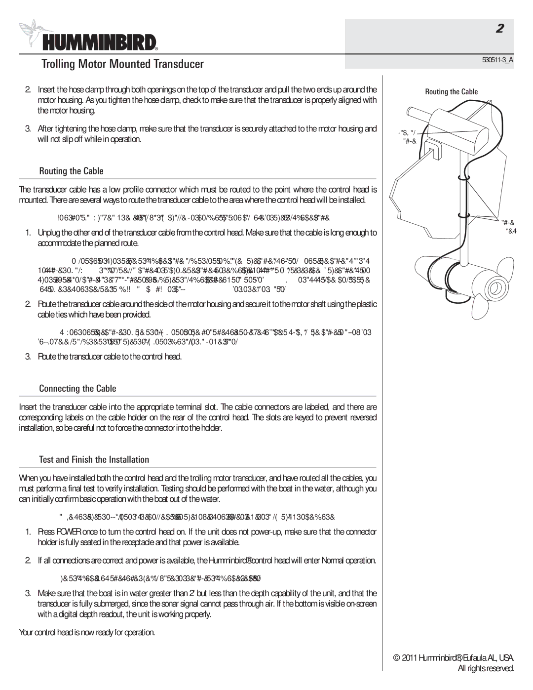
2.Route the transducercable around the side of the motor housing and secure it to the motor shaft using the plastic cable ties which have been provided.
NOTE: As you route the cable from the trolling motor to the boat, be sure to leave sufficient slack in the cable to allow for full movement and retraction of the trolling motor during normal operation.
3.Route the transducer cable to the control head.
3.Connecting the Cable
Insert the transducer cable into the appropriate terminal slot. The cable connectors are labeled, and there are corresponding labels on the cable holder on the rear of the control head. The slots are keyed to prevent reversed installation, so be careful not to force the connector into the holder.
4.Test and Finish the Installation
When you have installed both the control head and the trolling motor transducer, and have routed all the cables, you must perform a final test to verify installation. Testing should be performed with the boat in the water, although you can initially confirm basic operationwith the boat out of the water.
NOTE: Make sure the trollingmotor is
1.Press POWER once to turn the control head on. If the unit does not
2.If all connections are correct and power is available,the Humminbird® control head will enter Normal operation.
NOTE: The transducer must be submerged in water for reliable transducer detection.
3.Make sure that the boat is in water greater than 2' but less than the depth capability of the unit, and that the transducer is fully submerged, since the sonar signal cannot pass through air. If the bottom is visible
Your control head is now ready for operation.
Routing the Cable
Slack in ![]()
Cable
Cable
Ties
© 2011 Humminbird®, Eufaula AL, USA. All rights reserved.