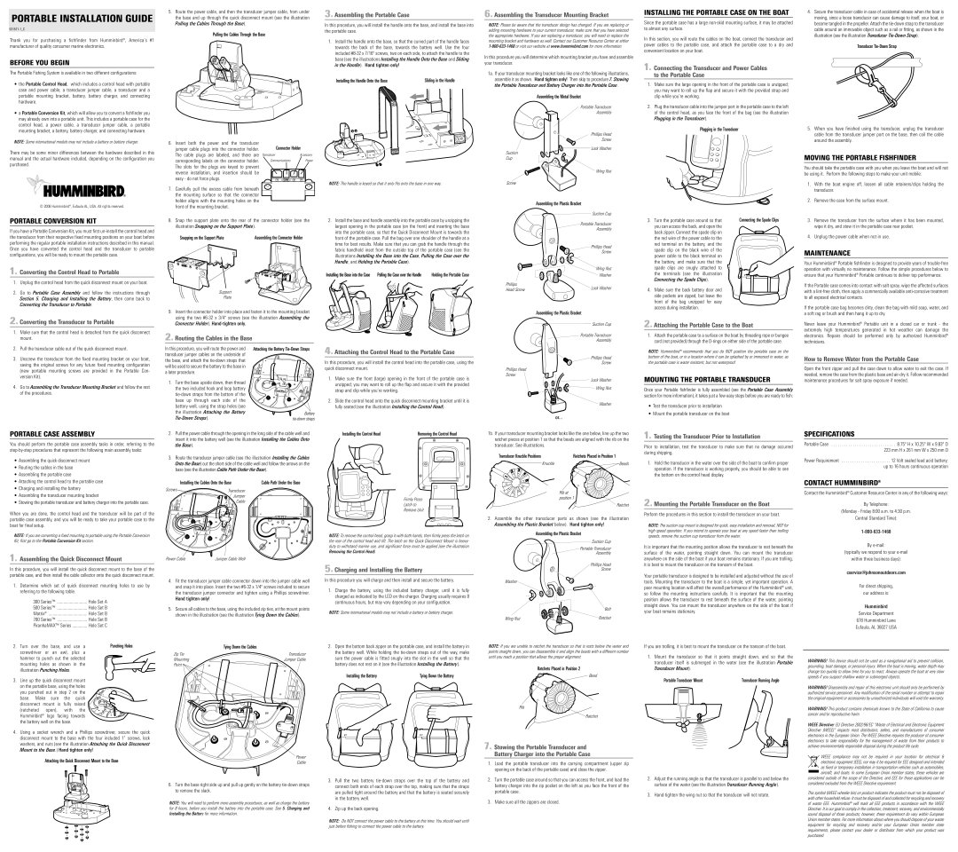
PORTABLE INSTALLATION GUIDE
Thank you for purchasing a fishfinder from Humminbird® , America’s #1 manufacturer of quality consumer marine electronics.
BEFORE YOU BEGIN
The Portable Fishing System is available in two different configurations:
•the Portable Control Head, which includes a control head with portable case and power cable, a transducer jumper cable, a transducer and a portable mounting bracket, battery, battery charger, and connecting hardware.
•a Portable Conversion Kit, which will allow you to convert a fishfinder you may already own into a portable unit. This includes a portable case for the control head, a power cable, a transducer jumper cable, a portable mounting bracket, a battery, battery charger, and connecting hardware.
NOTE: Some international models may not include a battery or battery charger.
There may be some minor differences between the hardware described in this manual and the actual hardware included, depending on the configuration you purchased.
© 2008 Humminbird®, Eufaula AL, USA. All rights reserved.
PORTABLE CONVERSION KIT
If you have a Portable Conversion Kit, you must first
1. Converting the Control Head to Portable
1.Unplug the control head from the quick disconnect mount on your boat.
2.Go to Portable Case Assembly and follow the instructions through Section 5. Charging and Installing the Battery, then come back to Converting the Transducer to Portable.
2. Converting the Transducer to Portable
1.Make sure that the control head is detached from the quick disconnect mount.
2.Pull the transducer cable out of the quick disconnect mount.
3.Unscrew the transducer from the fixed mounting bracket on your boat, saving the original screws for any future fixed mounting configuration (new portable mounting screws are provided in the Portable Con- version Kit).
4.Go to Assembling the Transducer Mounting Bracket and follow the rest of the procedures.
5.Route the power cable, and then the transducer jumper cable, from under the base and up through the quick disconnect mount (see the illustration Pulling the Cables Through the Base).
Pulling the Cables Through the Base
6. Insert both the power and the transducer | Connector Holder | |
jumper cable plugs into the connector holder. | ||
The cable plugs are labeled, and there are | Transducer | Accessory |
corresponding labels on the connector holder. | Communications | Power |
The slots for the plugs are keyed to prevent |
|
|
reverse installation, and insertion should be |
|
|
easy - do not force plugs. |
|
|
7. Carefully pull the excess cable from beneath the mounting surface so that the connector holder aligns with the mounting holes on the front of the mounting bracket.
8.Snap the support plate onto the rear of the connector holder (see the illustration Snapping on the Support Plate).
Snapping on the Support Plate | Assembling the Connector Holder |
Support
Plate
9.Insert the connector holder into place and fasten it to the mounting bracket using the two
2. Routing the Cables in the Base
In this procedure, you will route the power and | Attaching the Battery |
transducer jumper cables on the underside of |
|
the base, and attach the |
|
will be used to securethe battery to the base in |
|
a later procedure. |
|
1. Turn the base upside down, then thread |
|
the two included hook and loop battery |
|
| |
base up through each side of the |
|
battery well, using the strap holes (see |
|
the illustration Attaching the Battery | Battery |
3. Assembling the Portable Case
In this procedure, you will install the handle onto the base, and install the base into the portable case.
1.Install the handle onto the base, so that the curved part of the handle faces towards the back of the base, towards the battery well. Use the four included
Installing the Handle Onto the Base | Sliding in the Handle |
NOTE: The handle is keyed so that it only fits onto the base in one way.
2.Install the base and handle assembly into the portable case by unzipping the largest opening in the portable case (on the front) and inserting the base into the portable case, so that the Quick Disconnect Mount is towards the front of the portable case. Pull the bag over one shoulder of the handle at a time for best results. Make sure that you can grab the handle through the fabric handhold inset from the outside top of the portable case (see the illustrations Installing the Base into the Case, Pulling the Case over the Handle, and Holding the Portable Case).
Installingthe Base into the Case | Pullingthe Case over the Handle | Holding the Portable Case |
4. Attaching the Control Head to the Portable Case
In this procedure, you will install the control head into the portable case, using the quick disconnect mount.
1.Make sure the front (large) opening in the front of the portable case is unzipped; you may want to roll up the flap and secure it with the provided strap and clip while you’re working.
2.Slide the control head onto the quick disconnect mounting bracket until it is fully seated (see the illustration Installing the Control Head).
6. Assembling the Transducer Mounting Bracket
NOTE: Please be aware that the transducer design has changed. If you are replacing or adding mounting hardware to your current transducer, make sure that you have selected the appropriate hardware. If you are replacing a transducer, you will need to replace the mounting bracket and hardware as well. Contact our Customer Resource Center at either
In this procedure you will determine which mounting bracket you have and assemble your transducer.
1a. If your transducer mounting bracket looks like one of the following illustrations, assemble it as shown. Hand tighten only! Then skip to procedure 7. Stowing the Portable Transducer and Battery Charger into the Portable Case.
Assembling the Metal Bracket
Portable Transducer
Assembly
Phillips Head
Screw
Lock Washer
Suction
Cup
Wing Nut
Screw
Assembling the Plastic Bracket
![]() Suction Cup
Suction Cup
Portable Transducer
Assembly
Phillips Head
Screw
Wing Nut
Washer
Phillips | Lock Washer | |
Head Screw | ||
|
Assembling the Plastic Bracket
Suction Cup
Portable Transducer
Assembly
Phillips Head
Screw
Phillips Head
Screw
Lock Washer
![]()
![]()
![]()
![]() Wing Nut
Wing Nut
Washer
or...
INSTALLING THE PORTABLE CASE ON THE BOAT
Since the portable case has a large
In this section, you will route the cables on the boat, connect the transducer and power cables to the portable case, and attach the portable case to a dry and convenient location on your boat.
1. Connecting the Transducer and Power Cables to the Portable Case
1.Make sure the large opening in the front of the portable case is unzipped; you may want to roll up the flap and secure it with the provided strap and clip while you’re working.
2.Plug the transducer cable into the jumper port in the portable case to the left of the control head, as you face the front of the bag (see the illustration Plugging in the Transducer).
Plugging in the Transducer
3. Turn the portable case around so that | Connecting the Spade Clips |
you can access the back, and open the |
|
back zipper. Connect the spade clip on |
|
the red wire of the power cable to the |
|
red terminal on the battery, and the |
|
spade clip on the black wire of the |
|
power cable to the black terminal on |
|
the battery, and make sure that the |
|
spade clips are snugly attached to |
|
the terminals (see the illustration |
|
Connecting the Spade Clips). |
|
4. Make sure the back battery door and side pockets are zipped, but leave the front of the bag unzipped for easy access during installation.
2. Attaching the Portable Case to the Boat
1.Attach the portable case to a surface on the boat by threading rope or bungee cord (not provided) through the
NOTE: Humminbird® recommends that you do NOT position the portable case on the bottom of the boat, or in a location where it can be splashed by or immersed in water, as the portable case is water resistant, but not waterproof.
MOUNTING THE PORTABLE TRANSDUCER
Once your Portable fishfinder is fully assembled (see the Portable Case Assembly section for more information), it takes just a few easy steps before you are ready to fish:
•Test the transducer prior to installation
•Mount the portable transducer on the boat
4.Secure the transducer cable in case of accidental release when the boat is moving, since a loose transducer can cause damage to itself, your boat, or become tangled in the propeller. Attach the
Transducer
5.When you have finished using the transducer, unplug the transducer cable from the transducer jumper port on the base, then coil the cable around the assembly.
MOVING THE PORTABLE FISHFINDER
You should take the portable case with you when you leave the boat and will not be using it. Perform the following steps to make your unit mobile:
1.With the boat engine off, loosen all cable retainers/clips holding the transducer.
2.Remove the case from the surface mount.
3.Remove the transducer from the surface where it has been mounted, wipe it dry, and stow it in the portable case rear pocket.
4.Unplug the power cable when not in use.
MAINTENANCE
Your Humminbird® Portable fishfinder is designed to provide years of
If the Portable case comes into contact with salt spray, wipe the affected surfaces with a
If the portable case bag becomes dirty, clean the bag with mild soap, water, and a soft rag or brush and then hang it up to dry.
Never leave your Humminbird® Portable unit in a closed car or trunk - the extremely high temperatures generated in hot weather can damage the electronics. Repairs should be performed only by authorized Humminbird® technicians.
How to Remove Water from the Portable Case
Open the front zipper and pull the case down to allow water to exit the case. If needed, remove the case from the plastic base and
PORTABLE CASE ASSEMBLY
You should perform the portable case assembly tasks in order, referring to the
•Assembling the quick disconnect mount
•Routing the cables in the base
•Assembling the portable case
•Attaching the control head to the portable case
•Charging and installing the battery
•Assembling the transducer mounting bracket
•Stowing the portable transducer and battery charger into the portable case.
When you are done, the control head and the transducer will be part of the portable case assembly, and you will be ready to take your portable case to the
2.Pull the power cable through the opening in the long side of the cable well and insert it into the battery well (see the illustration Installing the Cables Onto the Base).
3.Route the transducer jumper cable (see the illustration Installing the Cables Onto the Base) out the short side of the cable well and follow the arrowson the base (see the illustration Cable Path Under the Base).
| Installing the Cables Onto the Base | Cable Path Under the Base |
Screws | Transducer |
|
| Jumper |
|
| Cable |
|
Installing the Control Head | Removing the Control Head |
Firmly Press
Latch to
Remove Unit
1b. If your transducer mounting bracket looks like the one below, line up the two ratchet pieces at position 1 so that the beads are aligned with the rib on the transducer. See illustrations.
Transducer Knuckle Positions | Ratchets Placed in Position 1 |
Knuckle | Beads |
Rib at position 1
Ratchet
2. Assemble the other transducer parts as shown (see the illustration |
1. Testing the Transducer Prior to Installation
Prior to installation, test the transducer to make sure that no damage occurred during shipping.
1.Hold the transducer in the water over the side of the boat to confirm proper operation. If the transducer is working properly, you should be able to see the bottom on the control head display.
2. Mounting the Portable Transducer on the Boat
Perform the procedures in this section to install the transducer on your boat.
SPECIFICATIONS
Portable Case | . . . . . . 8.75" H x 10.25" W x 9.83" D |
| 223 mm H x 261 mm W x 250 mm D |
Power Requirement . . . . . . . . . . . . . . . . . . . . . . . 12 Volt sealed lead acid battery; up to 16 hours continuous operation
CONTACT HUMMINBIRD®
Contact the Humminbird® Customer Resource Center in any of the following ways:
By Telephone:
(Monday - Friday 8:00 a.m. to 4:30 p.m.
Central Standard Time):
boat for final setup.
NOTE: If you are converting a fixed mounting to portable using the Portable Conversion Kit, first go to the Portable Conversion Kit section.
1. Assembling the Quick Disconnect Mount
In this procedure, you will install the quick disconnect mount to the base of the portable case, and then install the cable collector onto the quick disconnect mount.
1.Determine which set of quick disconnect mounting holes to use by referring to the following table.
300 Series™ | Hole Set A |
500 Series™ | Hole Set B |
Matrix® | Hole Set B |
700 Series™ | Hole Set B |
PiranhaMAX™ Series | Hole Set C |
|
| NOTE: To remove the control head, grasp it with both hands, then firmly press the latch on | |
|
| the rear of the control head and lift. The latch on the Quick Disconnect Mount is heavy- | |
|
| duty to withstand marine use, and significant force must be applied (see the illustration | |
|
| Removing the Control Head). | |
Power Cable | Jumper Cable Well |
| |
|
| 5. Charging and Installing the Battery | |
4. Fit the transducer jumper cable connector down into the jumper cable well | In this procedure you will charge and then install and secure the battery. | ||
and snap it into place. Insert the two | 1. Charge the battery, using the included battery charger, until it is fully | ||
the transducer jumper connector and tighten using a Phillips screwdriver. | |||
charged as indicated by the LED on the charger. Charging usually requires 8 | |||
Hand tighten only! |
| ||
| continuous hours, but may vary depending on your configuration. | ||
|
| ||
5. Secure all cables to the base, using the included zip ties, at the mount points | NOTE: Some international models may not include a battery or battery charger. | ||
shown in the illustration (see the illustration Tying Down the Cables). | |||
| |||
Assembling the Plastic Bracket below). Hand tighten only! |
Assembling the Plastic Bracket
Suction Cup
Portable Transducer
Assembly
Phillips Head
Screw
Washer
Bolt
Wing Nut | Ratchet |
NOTE: The suction cup mount is designed for quick, easy installation and removal, NOT for high speed operation. If you intend to operate your boat at any speed faster than trolling speeds, remove the suction cup transducer from the water.
It is important that the mounting position allows the transducer to rest beneath the surface of the water, pointing straight down. You can mount the transducer anywhere on the side of the boat if your boat remains stationary. If you are trolling, it is best to mount the transducer on the transom of the boat.
Your portable transducer is designed to be installed and adjusted without the use of tools. Mounting the transducer to the boat is a simple, yet important operation. A poor mounting location will affect the overall performance of the Humminbird® unit, so follow the mounting instructions carefully. It is important that the mounting position allows the transducer to rest beneath the surface of the water, pointing straight down. You can mount the transducer anywhere on the side of the boat if your boat remains stationary.
By
(typically we respond to your
within three business days):
cservice@johnsonoutdoors.com
For direct shipping,
our address is:
Humminbird
Service Department
678 Humminbird Lane
Eufaula, AL 36027 USA
2. Turn over the base, and | use a | Punching Holes | ||
screwdriver or an awl, plus a |
| |||
hammer to punch out the selected |
| |||
mounting holes as shown in the |
| |||
illustration Punching Holes. |
|
| ||
3. Line up the quick disconnect mount |
| |||
on the portable base, using the holes |
| |||
you punched out in step 2 on the |
| |||
base. Make | sure | the | quick |
|
disconnect mount is fully raised |
| |||
(ratcheted | open), | with | the |
|
Humminbird® | logo facing towards |
| ||
the battery well on the base.
4.Using a socket wrench and a Phillips screwdriver, secure the quick disconnect mount to the base with the four included 1” screws, lock washers, and nuts (see the illustration Attaching the Quick Disconnect Mount to the Base.) Hand tighten only!
Attaching the Quick Disconnect Mount to the Base
| Tying Down the Cables |
Zip Tie | Transducer |
Mounting | Jumper Cable |
Point |
|
Power
Cable
6.Turn the base right side up and pull up gently on the battery
NOTE: You will need to perform more assembly procedures, as well as charge the battery for 8 hours, before you install the battery into the portable case. See 5. Charging and Installing the Battery for more information.
2.Open the bottom back zipper on the portable case, and install the battery in the battery well. While holding the
Installing the Battery | Tying Down the Battery |
3.Pull the two battery
4.Zip up the back opening.
NOTE: Do NOT connect the power cable to the battery at this time. You should wait until just before fishing to connect the power cable to the battery.
NOTE: If you are unable to ratchet the transducer so that is rests below the water and points straight down, you can disassemble it and align the beads with a different number until you reach a position that allows the proper alignment.
Ratchets Placed in Position 2
Bead
Rib
Ratchet
7. Stowing the Portable Transducer and Battery Charger into the Portable Case
1.Load the portable transducer into the carrying compartment (upper zip opening on the back of the portable case) and close the zipper.
2.Turn the portable case around so that you can access the front, and load the battery charger into the zip pocket on the left as you face the front of the portable case.
3.Make sure all the zippers are closed.
If you are trolling, it is best to mount the transducer on the transom of the boat.
1.Mount the transducer so that it points straight down, and so that the transducer itself is submerged in the water (see the illustration Portable Transducer Mount).
Portable Transducer Mount | Transducer Running Angle |
2.Adjust the running angle so that the transducer is parallel to and below the surface of the water (see the illustration Transducer Running Angle).
3.
WARNING! This device should not be used as a navigational aid to prevent collision, grounding, boat damage, or personal injury. When the boat is moving, water depth may change too quickly to allow time for you to react. Always operate the boat at very slow speeds if you suspect shallow water or submerged objects.
WARNING! Disassembly and repair of this electronic unit should only be performed by authorized service personnel. Any modification of the serial number or attempt to repair the original equipment or accessories by unauthorized individuals will void the warranty.
WARNING! This product contains chemicals known to the State of California to cause cancer and/or reproductive harm.
WEEE Directive: EU Directive 2002/96/EC “Waste of Electrical and Electronic Equipment Directive (WEEE)” impacts most distributors, sellers, and manufacturers of consumer electronics in the European Union. The WEEE Directive requires the producer of consumer electronics to take responsibility for the management of waste from their products to achieve environmentally responsible disposal during the product life cycle.
WEEE compliance may not be required in your location for electrical & electronic equipment (EEE), nor may it be required for EEE designed and intended as fixed or temporary installation in transportation vehicles such as automobiles, aircraft, and boats. In some European Union member states, these vehicles are
considered outside of the scope of the Directive, and EEE for those applications can be considered excluded from the WEEE Directive requirement.
This symbol (WEEE wheelie bin) on product indicates the product must not be disposed of with other household refuse. It must be disposed of and collected for recycling and recovery of waste EEE. Humminbird® will mark all EEE products in accordance with the WEEE Directive. It is our goal to comply in the collection, treatment, recovery, and environmentally sound disposal of those products; however, these requirement do vary within European Union member states. For more information about where you should dispose of your waste equipment for recycling and recovery and/or your European Union member state requirements, please contact your dealer or distributor from which your product was purchased.