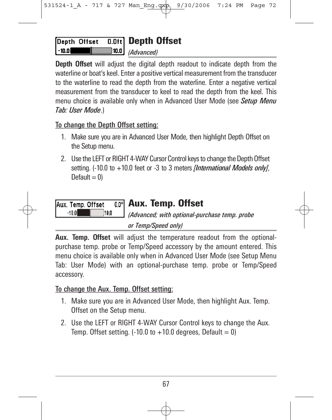
700 Series Operations Manual
531524-1A - 717 & 727 ManEng.qxp 9/30/2006 723 PM Page
Thank You
Table of Contents
Accessory Bus
Powering Up the Unit
How Sonar Works
Table of Contents
Alarms Menu Tab
Setup Menu Tab
Sonar X-Press Menu
Table of Contents
Accessories Menu Tab
Troubleshooting
700 Series Fishing System Accessories
How Sonar Works
Peak to Peak measures power output at the highest points
DualBeam PLUS Sonar
531524-1A - 717 & 727 ManEng.qxp 9/30/2006 723 PM Page
QuadraBeam PLUS Sonar
with optional-purchase QuadraBeam PLUS transducer
WideSide Sonar
with optional-purchase WideSide transducer
Universal Sonar
What’s On the Display
Timer - elapsed time with Temp/Speed Accessory or GPS Receiver
531524-1A - 717 & 727 ManEng.qxp 9/30/2006 723 PM Page
Bait Ball Hard Bottom Rocky Bottom
83 kHz, Wide Beam Hollow Fish Symbol
200 kHz, Narrow Beam Shaded Fish Symbol
ormation
531524-1A - 717 & 727 ManEng.qxp 9/30/2006 723 PM Page
Views
The views available on your Fishing System are Sonar View Zoom View
200/83 kHz Split Sonar View Big Digits View Circular Flasher View
Side Beam View WideSide View
Sonar View
Sonar View
Understanding Sonar History
531524-1A - 717 & 727 ManEng.qxp 9/30/2006 723 PM Page
Real Time Sonar RTS Window
Freeze Frame and Cursor
531524-1A - 717 & 727 ManEng.qxp 9/30/2006 723 PM Page
Bottom Presentation
Inverse is a method where weak returns are shown with dark pixels and strong returns with lighter pixels. This has the benefit of ensuring that weak signals will be clearly visible on the display
Bottom Black displays all pixels below the bottom contour as black, regardless of signal strength. This has the benefit of providing a high contrast between the bottom and other sonar returns on the display. Any targets such as fish, structure and thermoclines will be shown using the Structure ID method
Sonar Zoom View
Sonar Zoom View
200/83 kHz Split Sonar View
531524-1A - 717 & 727 ManEng.qxp 9/30/2006 723 PM Page
200/83 kHz Split Sonar View
Big Digits View
Big Digits View
Circular Flasher View
531524-1A - 717 & 727 ManEng.qxp 9/30/2006 723 PM Page
Side Beam View
with optional-purchase QuadraBeam PLUS transducer
Side Beam View, Classic Layout
Side Beam View, Slanted Layout
WideSide View
with optional-purchase WideSide transducer
POWER/LIGHT Key
Key Functions
VIEW Key
MENU Key
4-WAY Cursor Control Key
The MENU key is used to access the menu system
EXIT Key
If an alarm is sounding, pressing EXIT will cancel the alarm
The EXIT key has multiple functions, depending on the situation
Pressing EXIT will cycle through the available views in reverse order
Accessory Bus
Powering Up the Unit
531524-1A - 717 & 727 ManEng.qxp 9/30/2006 723 PM Page
727 Title Screen
The Menu System
Sonar Tab Normal Mode Sonar Tab Advanced Mode
Start-Up Options Menu
Normal Operation
Exit Normal operation by powering your Fishing System off
Options menu
Simulator
Exit the Simulator by powering your Fishing System off
System Status
Self Test
Self Test Accessory Test
Accessory Test
PC Connect
Accessory Test lists the accessories connected to the system
Exit System Status by powering your Fishing System off
Sonar X-Press Menu
Mode when in Sonar, Split Sonar, Big Digits and Circular
531524-1A - 717 & 727 ManEng.qxp 9/30/2006 723 PM Page
NOTE Upper Range only appears in Advanced User
Side
To adjust the Side
WideSide transducer WideSide view only
Sensitivity
To adjust the Sensitivity
1. Highlight Sensitivity on the Sonar X-Press Menu
Upper Range
To adjust the Upper Range
Advanced Sonar, Split Sonar, Big Digits and
Circular Flasher Views only
Lower Range
To adjust the Lower Range
1. Highlight Lower Range on the Sonar X-Press Menu
Side Beam Range
To adjust the Side Beam Range
WideSide transducer WideSide view only
Chart Speed
Bottom View
To adjust the Chart Speed
1. Highlight Chart Speed on the Sonar X-Press Menu
Quad Layout
To adjust the Bottom View
To adjust the Quad Layout
1. Highlight Bottom View on the Sonar X-Press Menu
Zoom Level
Bottom Lock
To adjust the Quad Layout
1. Highlight Quad Layout on the Sonar X-Press menu
Bottom Range
To adjust the Bottom Range
Sonar Zoom View only, when Bottom Lock is On
Sonar Menu Tab
531524-1A - 717 & 727 ManEng.qxp 9/30/2006 724 PM Page
Sonar Menu
Beam Select
To use Beam Select 1. Highlight Beam Select on the Sonar main menu
Fish ID+
To turn Fish ID+ on or off
1. Highlight Fish ID+ on the Sonar main menu
Fish ID Sensitivity
To change the Fish ID Sensitivity setting
To change the RTS Window setting
Real Time Sonar RTS Window
Zoom Width
83 kHz Sensitivity
To change the Zoom Width Setting
1. Highlight Zoom Width on the Sonar main menu
455 kHz Sensitivity
To change the 455 kHz Sensitivity setting
Advanced with QuadraBeam PLUS transducer
WideSide Sensitivity
To change the WideSide Sensitivity setting
Advanced with WideSide transducer
Depth Lines
To change the Depth Lines setting
Surface Clutter
To change the Surface Clutter setting
Advanced
Noise Filter
Max Depth
To change the Noise Filter setting
Advanced
Water Type
To change the Max Depth setting
To change the Water Type setting
Transducer Select
To change the selected Transducer
1. Highlight Transducer Select on the Sonar Main menu
Alarms Menu Tab
Alarms Menu
531524-1A - 717 & 727 ManEng.qxp 9/30/2006 724 PM Page
Depth Alarm
Fish ID Alarm
To change the Depth Alarm setting
1. Highlight Depth Alarm on the Alarms main menu
Low Battery Alarm
Aux. Temp. Alarm
To change the Low Battery Alarm setting
1. Highlight Low Battery Alarm on the Alarms main menu
Temp Alarm
Alarm Tone
To change the Temp Alarm setting
1. Highlight Temp Alarm on the Alarms main menu
Setup Menu Tab
Setup Menu
531524-1A - 717 & 727 ManEng.qxp 9/30/2006 724 PM Page
Units - Depth
Units - Temp
Units - Distance
depth-related readouts To change the Units - Depth setting
Units - Speed
User Mode
Language
To change the Units - Speed setting
Triplog Reset
Restore Defaults
To Reset Triplog 1. Highlight Reset Triplog on the Setup menu
2. Use the RIGHT 4-WAY Cursor Control key to initiate Triplog Reset
Select Readouts
Voltage
Advanced, Sonar view only
2. Use the RIGHT 4-WAY Cursor Control key to initiate this procedure
Default Sonar View
To Select Readouts
Customized Sonar View
Depth Offset
Aux. Temp. Offset
To change the Depth Offset setting
To change the Aux. Temp. Offset setting
Temp Offset
Speed Calibration
To change the Temp Offset setting
To change the Speed Calibration setting
Digits Format
To change the Digits Format setting
NMEA Output
The following NMEA sentences are output when NMEA Output is turned On
DPT- Depth MTW - Water Temperature GLL - Lat/Lon Position
GGA - GPS Fix Data RMC - Recommended Minimum Specific GNSS Data
Views Menu Tab
WideSide View
To change the view status of any view
1. Highlight the View main menu tab
Accessories Menu Tab
Troubleshooting
700 Series Doesn’t Power Up
700 Series Defaults to Simulator with a Transducer Attached
The power cable is properly connected to the 700 Series control head
Display Problems
Problem
Low battery voltage may be affecting the power of signal transmission
Possible Cause
Finding the Cause of Noise
the engine wiring
Isolation
The boat’s engine
700 Series Fishing System Accessories
Wireless Sonar Link WSL purchase the Wireless Sonar Link WSL accessory to receive remote sonar signals from a SmartCast Remote Sonar Sensor RSS. Radio signals from the RSS are received by the WSL and transmitted over the Accessory Bus to the 700 Series Fishing System
531524-1A - 717 & 727 ManEng.qxp 9/30/2006 724 PM Page
Specifications
Operating Frequency . . . . . . 200 kHz and 83 kHz DualBeam PLUS
POLICY ON ENVIRONMENTAL COMPLIANCE It is the intention of Humminbird to be a good corporate citizen and comply and meet all known and applicable environmental regulations in the areas and countries where our products are sold. We will promote and implement environmentally sound processes in support of national and international regulations
531524-1A - 717 & 727 ManEng.qxp 9/30/2006 724 PM Page
Glossary
Sonar Terms
Page
Feature Memory Feature Memory is a Humminbird feature that retains the users menu settings in permanent memory. Settings are retained even when the unit is powered off indefinitely
531524-1A - 717 & 727 ManEng.qxp 9/30/2006 724 PM Page
Hydrodynamic noise can be overcome by proper transducer installation. Many Humminbird products have a Noise Filter menu setting that allows the user to clear the screen of noise that is difficult to eliminate
Receiver See Transmitter
Page
Structure Structure is a general term for objects on the bottom that present a discontinuity and are a likely attractor for fish. This includes bottom contour features drop-offs, humps, and holes, standing structure stumps, timbers, brush piles and a wide range of other potential objects sunken boats, reefs. Humminbird units excel at showing structure with great detail over a wider area due to unique sonar configurations developed for the angler
Page
Page
Contact Humminbird
custserv@johnsonoutdoors.com
Humminbird