
40955-01 specifications
The Hunter Fan 40955-01 is a notable ceiling fan designed to enhance both functionality and aesthetics in any space. Renowned for its classic yet modern design, this ceiling fan fits seamlessly into various home environments, from contemporary to traditional settings.One of the standout features of the Hunter Fan 40955-01 is its powerful motor, which delivers exceptional airflow while maintaining quiet operation. The fan is equipped with a WhisperWind technology, ensuring that it can circulate air without the disruptive noise that often accompanies other high-performance fan models. This makes it an ideal choice for bedrooms, living rooms, or any area where a peaceful atmosphere is desired.
The fan boasts five sleek blades crafted from high-quality materials, ensuring durability and longevity. These blades are designed with an aerodynamic shape to maximize airflow efficiency, contributing to a comfortable home climate throughout the year. The blade pitch and size are thoughtfully engineered to provide optimal air circulation, making it effective in both cooling and providing warmth in winter months.
In terms of design, the Hunter Fan 40955-01 features a timeless finish that complements any decor. Available in various color options, including bronze and brushed nickel, it can easily match different interiors. The fan's elegant silhouette adds a touch of sophistication to ceiling spaces, elevating the overall ambiance.
Technology is also a significant aspect of this fan. It includes a convenient remote control, allowing users to operate the fan's speed and light settings from anywhere in the room. This added convenience is perfect for those who want a tailored climate without the need to get up frequently. Additionally, the fan is compatible with smart home systems, allowing for app-based control and integration with other smart devices.
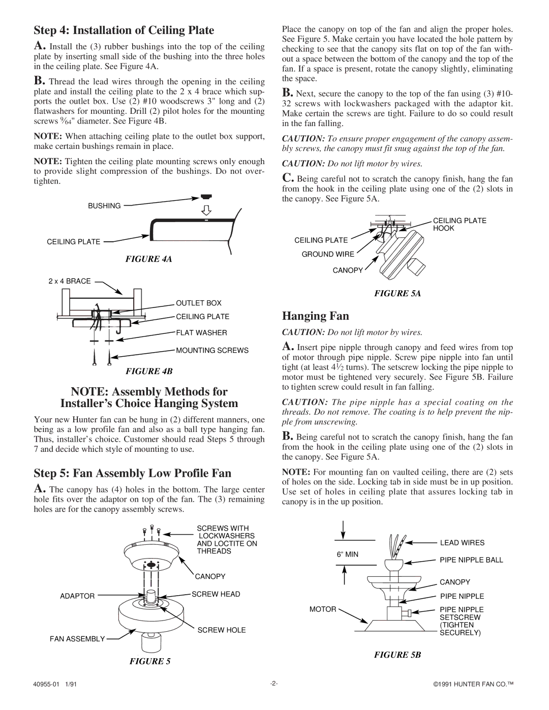
Installation of the Hunter Fan 40955-01 is straightforward, thanks to its user-friendly design and included instructions. The fan is versatile and can be mounted in various orientations, including flush-mounted or standard mount, depending on the user's needs.
Overall, the Hunter Fan 40955-01 brings together style, functionality, and innovative technology, making it an excellent choice for anyone seeking to improve the air circulation and aesthetics of their living space.