8
installing the switch housing
attaching the upper switch housing
1.Partially install two
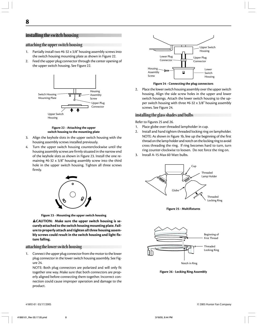
2.Feed the upper plug connector through the center opening of the upper switch housing. See Figure 22.
Lower Plug
Connector
Housing
Assembly
Screw
Upper Switch
Housing
Upper Plug
Connector
Lower
Switch
Housing
Switch Housing | Housing |
Assembly | |
Mounting Plate | Screw |
Upper Plug
Connector
Upper Switch
Housing
Figure 22 - Attaching the upper
switch housing to the mounting plate
3.Align the keyhole slots in the upper switch housing with the housing assembly screws installed previously.
4.Turn the upper switch housing counterclockwise until the housing assembly screws are firmly situated in the narrow end of the keyhole slots as shown in Figure 23. Install the one re- maining
Figure 23 - Mounting the upper switch housing
![]() CAUTION: Make sure the upper switch housing is se- curely attached to the switch housing mounting plate. Fail- ure to properly attach and tighten all three housing assem- bly screws could result in the switch housing and light fix- ture falling.
CAUTION: Make sure the upper switch housing is se- curely attached to the switch housing mounting plate. Fail- ure to properly attach and tighten all three housing assem- bly screws could result in the switch housing and light fix- ture falling.
attaching the lower switch housing
1.Connect the upper plug connector from the motor to the lower plug connector in the lower switch housing assembly. See Fig- ure 24.
NOTE: Both plug connectors are polarized and will only fit together one way. Make sure that both connectors are prop- erly aligned before connecting them together. Incorrect con- nection could cause improper operation and damage to the product.
Figure 24 - Connecting the plug connectors
2.Place the lower switch housing assembly over the upper switch housing. Align the side screw holes in the upper and lower switch housings. Attach the lower switch housing to the up- per switch housing with three
installing the glass shades and bulbs
Refer to Figures 25 and 26.
1.Place globe over threaded lampholder in cup.
2.Install and hand tighten threaded locking ring on lampholder. NOTE: As shown in Figure 1b, line up the beginning of the first thread on the lamp holder and notch on the locking ring to avoid cross threading the ring. If ring becomes hard to turn, turn ring
3.Install A-15 Max 60 Watt bulbs.
Cup
Threaded
Lamp Holder
Globe ![]()
Threaded
Locking Ring
Figure 25 - Multifixtures
Beginning of |
First Thread |
Threaded |
Locking Ring |
Notch in Ring
Figure 26 - Locking Ring Assembly
© 2005 Hunter Fan Company
8 | 3/18/05, 8:44 PM |