5
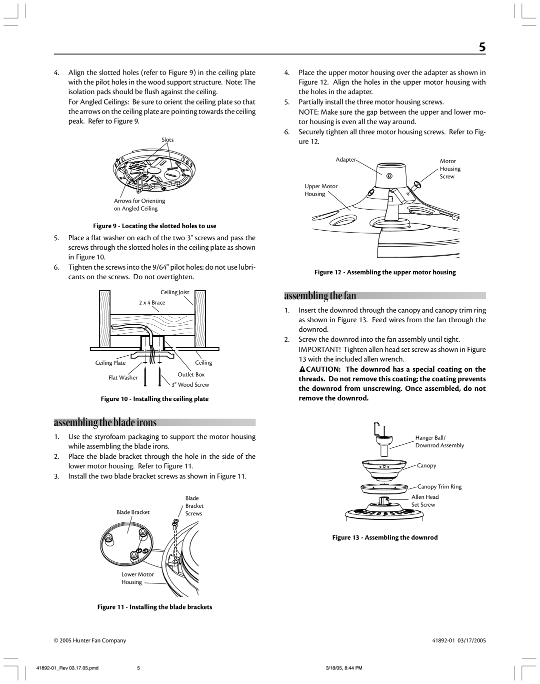
4.Align the slotted holes (refer to Figure 9) in the ceiling plate with the pilot holes in the wood support structure. Note: The isolation pads should be flush against the ceiling.
For Angled Ceilings: Be sure to orient the ceiling plate so that the arrows on the ceiling plate are pointing towards the ceiling peak. Refer to Figure 9.
Slots
Arrows for Orienting on Angled Ceiling
Figure 9 - Locating the slotted holes to use
5.Place a flat washer on each of the two 3" screws and pass the screws through the slotted holes in the ceiling plate as shown in Figure 10.
6.Tighten the screws into the 9/64" pilot holes; do not use lubri- cants on the screws. Do not overtighten.
Ceiling Joist
2 x 4 Brace
Ceiling Plate | Ceiling | |
Flat Washer | Outlet Box | |
3” Wood Screw | ||
|
Figure 10 - Installing the ceiling plate
assembling the blade irons
1.Use the styrofoam packaging to support the motor housing while assembling the blade irons.
2.Place the blade bracket through the hole in the side of the lower motor housing. Refer to Figure 11.
3.Install the two blade bracket screws as shown in Figure 11.
| Blade |
Blade Bracket | Bracket |
Screws |
Lower Motor
Housing
Figure 11 - Installing the blade brackets
© 2005 Hunter Fan Company
4.Place the upper motor housing over the adapter as shown in Figure 12. Align the holes in the upper motor housing with the holes in the adapter.
5.Partially install the three motor housing screws.
NOTE: Make sure the gap between the upper and lower mo- tor housing is even all the way around.
6.Securely tighten all three motor housing screws. Refer to Fig- ure 12.
Adapter | Motor |
| Housing |
| Screw |
Upper Motor |
|
Housing |
|
Figure 12 - Assembling the upper motor housing
assembling the fan
1.Insert the downrod through the canopy and canopy trim ring as shown in Figure 13. Feed wires from the fan through the downrod.
2.Screw the downrod into the fan assembly until tight. IMPORTANT! Tighten allen head set screw as shown in Figure 13 with the included allen wrench.
![]() CAUTION: The downrod has a special coating on the threads. Do not remove this coating; the coating prevents
CAUTION: The downrod has a special coating on the threads. Do not remove this coating; the coating prevents
the downrod from unscrewing. Once assembled, do not remove the downrod.
Hanger Ball/
Downrod Assembly
Canopy
Canopy Trim Ring
Allen Head
Set Screw
Figure 13 - Assembling the downrod
5 | 3/18/05, 8:44 PM |