41897-01 specifications
The Hunter Fan 41897-01 is a ceiling fan that combines aesthetic appeal with functionality, making it an ideal choice for both modern and traditional interiors. Known for its reliable performance and stylish design, this ceiling fan has garnered attention from homeowners looking to enhance their living spaces.One of the standout features of the Hunter Fan 41897-01 is its WhisperWind motor technology. This innovative motor design ensures a powerful airflow while operating quietly, making it perfect for bedrooms, living rooms, or any other area where tranquility is desired. The fan offers three speeds, allowing users to customize their comfort level depending on the average room temperature or personal preference.
Another noteworthy characteristic is its traditional blade shape combined with a contemporary finish. The fan comes with five blades that are carefully crafted to provide optimal air movement. These blades are usually available in a dark wood finish, which adds a touch of elegance to the fan’s overall design. The fan’s 52-inch blade span makes it suitable for medium to large rooms, efficiently dispersing air to maintain a comfortable environment.
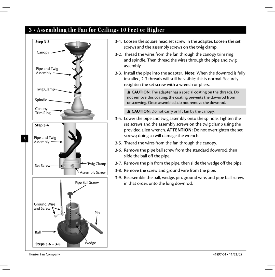
One of the most user-friendly features of the Hunter Fan 41897-01 is its easy installation process. It comes with detailed instructions and user-friendly components, making it a straightforward DIY project for most homeowners. Additionally, this ceiling fan is designed with a universal mount, which enhances installation versatility, allowing it to be mounted on flat or sloped ceilings.
Durability is another key consideration with the Hunter Fan 41897-01. Constructed from high-quality materials, this ceiling fan is designed to withstand the test of time. Its rust-resistant finish and robust blades make it suitable for various settings, including indoor and covered outdoor spaces.
The fan is also compatible with Hunter’s smart home technology, allowing users to control the fan through a mobile app or voice commands when integrated with smart home systems. This level of automation adds convenience and enhances comfort, as users can adjust fan settings without needing to reach for the pull chain or remote.
In summary, the Hunter Fan 41897-01 stands out for its combination of elegant design, advanced features, and durability. Its WhisperWind motor technology, easy installation, and compatibility with smart technologies make it a worthy addition to any home, offering both style and comfort.

