
41936-01 specifications
The Hunter Fan 41936-01 is a striking addition to any home décor, combining style, functionality, and advanced technology. This ceiling fan is designed to provide optimal airflow while enhancing the aesthetics of your living space, making it an ideal choice for both design enthusiasts and functionality seekers.One of the standout features of the Hunter Fan 41936-01 is its modern design. With a sleek finish and elegant lines, it can seamlessly fit into various interior designs, whether contemporary, industrial, or rustic. The fan is available in a range of color options, allowing homeowners to select a model that perfectly complements their existing décor.
Equipped with a powerful yet quiet motor, the Hunter Fan 41936-01 provides efficient airflow for any room size. Its whisper-quiet operation ensures that the fan can cool your space without disruptive noise, creating a more comfortable environment. The fan has multiple speed settings, allowing users to adjust airflow according to their comfort level.
Another noteworthy aspect of this ceiling fan is its integrated LED lighting. The dimmable LED bulbs offer energy efficiency while providing bright, quality illumination for your room. This dual functionality of lighting and cooling makes it a practical addition to any space, whether it be a living room, bedroom, or home office.
Hunter's innovative technology includes the use of a reversible motor, which allows the fan to spin in both directions. This feature is particularly advantageous during different seasons; the fan can provide a refreshing breeze in the summer and circulate warm air during the winter months, significantly enhancing the fan's year-round usability.
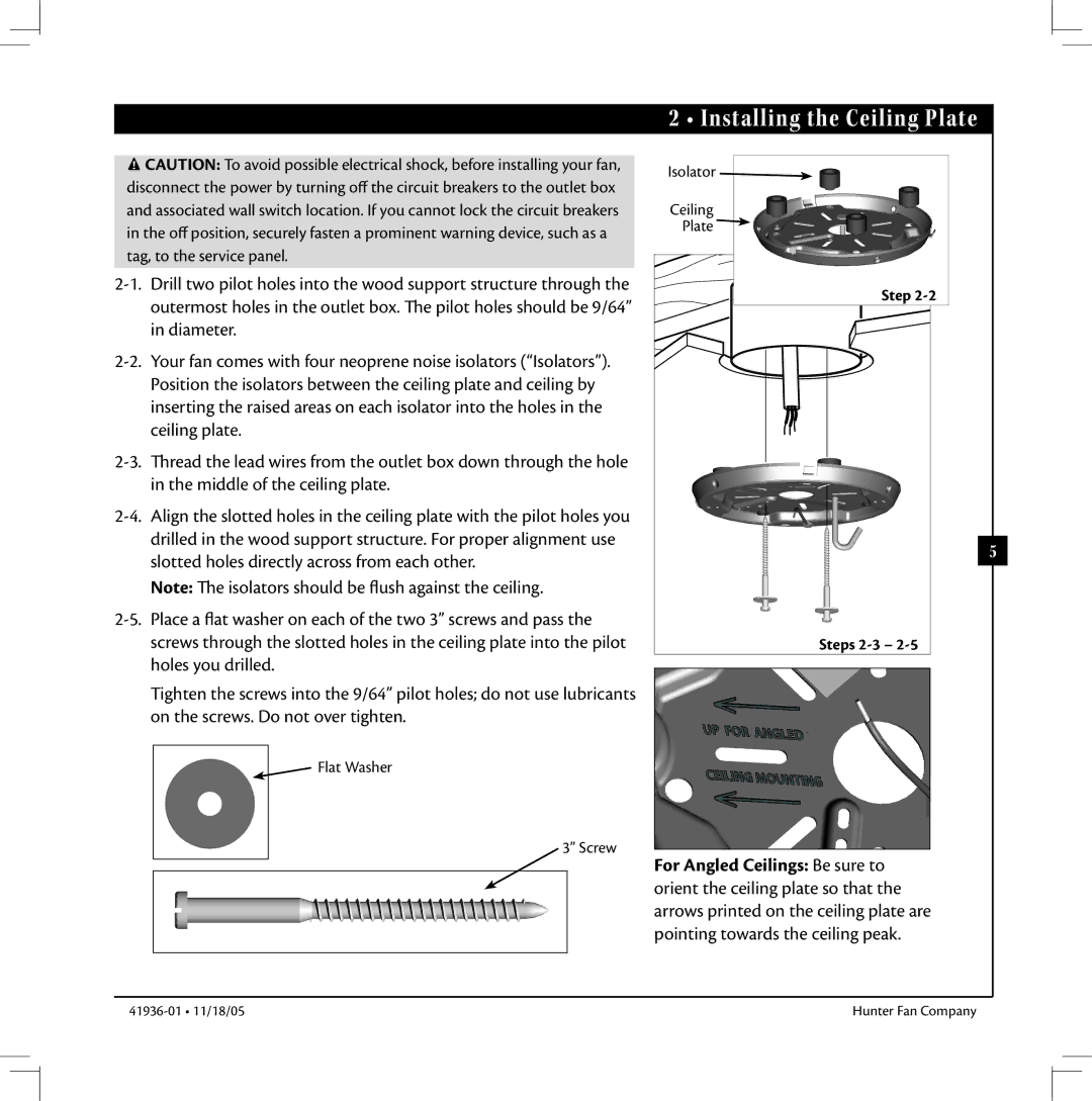
Installation is made easier with the fan's user-friendly design and detailed instructions. Most homeowners can self-install the fan with minimal tools required, making it a hassle-free choice for those looking to upgrade their space.
In terms of energy efficiency, the Hunter Fan 41936-01 is compliant with ENERGY STAR standards, ensuring that it operates with lower energy consumption, contributing to reduced electricity bills. This eco-friendly approach aligns with modern demands for sustainable home solutions.
To summarize, the Hunter Fan 41936-01 is an exceptional ceiling fan that combines aesthetic appeal with innovative features. From its stylish design to its efficient motor and integrated lighting, it is a versatile and practical choice for enhancing comfort and ambiance in any room. With its advanced functionalities and ease of installation, it truly meets the needs of modern homeowners looking to elevate their living spaces.