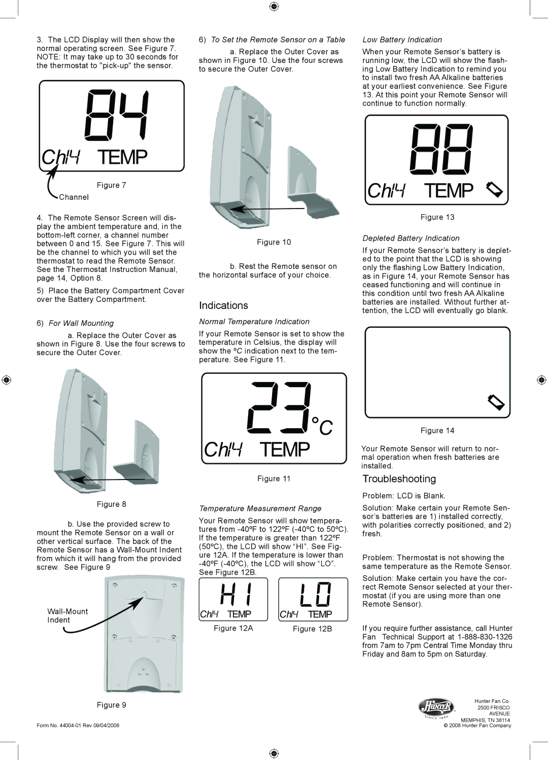
3.The LCD Display will then show the normal operating screen. See Figure 7.
NOTE: It may take up to 30 seconds for the thermostat to
Ch
 TEMP
TEMP
Figure 7
Channel
4.The Remote Sensor Screen will dis- play the ambient temperature and, in the
5)Place the Battery Compartment Cover over the Battery Compartment.
6)For Wall Mounting
a. Replace the Outer Cover as shown in Figure 8. Use the four screws to secure the Outer Cover.
Figure 8
b. Use the provided screw to mount the Remote Sensor on a wall or other vertical surface. The back of the Remote Sensor has a
Indent
Figure 9
Form No.
6)To Set the Remote Sensor on a Table
a. Replace the Outer Cover as shown in Figure 10. Use the four screws to secure the Outer Cover.
Figure 10
b. Rest the Remote sensor on the horizontal surface of your choice.
Indications
Normal Temperature Indication
If your Remote Sensor is set to show the temperature in Celsius, the display will show the ºC indication next to the tem- perature. See Figure 11.
![]() C
C
Ch![]()
![]()
![]() TEMP
TEMP
Figure 11
Temperature Measurement Range
Your Remote Sensor will show tempera- tures from
Ch TEMP | Ch TEMP |
Figure 12A | Figure 12B |
Low Battery Indication
When your Remote Sensor’s battery is running low, the LCD will show the flash- ing Low Battery Indication to remind you to install two fresh AA Alkaline batteries at your earliest convenience. See Figure
13.At this point your Remote Sensor will continue to function normally.
Ch![]()
![]()
![]() TEMP
TEMP ![]()
Figure 13
Depleted Battery Indication
If your Remote Sensor’s battery is deplet- ed to the point that the LCD is showing only the flashing Low Battery Indication, as in Figure 14, your Remote Sensor has ceased functioning and will continue in this condition until two fresh AA Alkaline batteries are installed. Without further at- tention, the LCD will eventually go blank.
Figure 14
Your Remote Sensor will return to nor- mal operation when fresh batteries are installed.
Troubleshooting
Problem: LCD is Blank.
Solution: Make certain your Remote Sen- sor’s batteries are 1) installed correctly, with polarities correctly positioned, and 2) fresh.
Problem: Thermostat is not showing the same temperature as the Remote Sensor.
Solution: Make certain you have the cor- rect Remote Sensor selected at your ther- mostat (if you are using more than one Remote Sensor).
If you require further assistance, call Hunter Fan Technical Support at
Hunter Fan Co.
2500 FRISCO AVENUE MEMPHIS, TN 38114
© 2008 Hunter Fan Company