I n s t a l l a t i o n | G u i d e |
ENGLISH
See page 2
Español
Vea la página 21
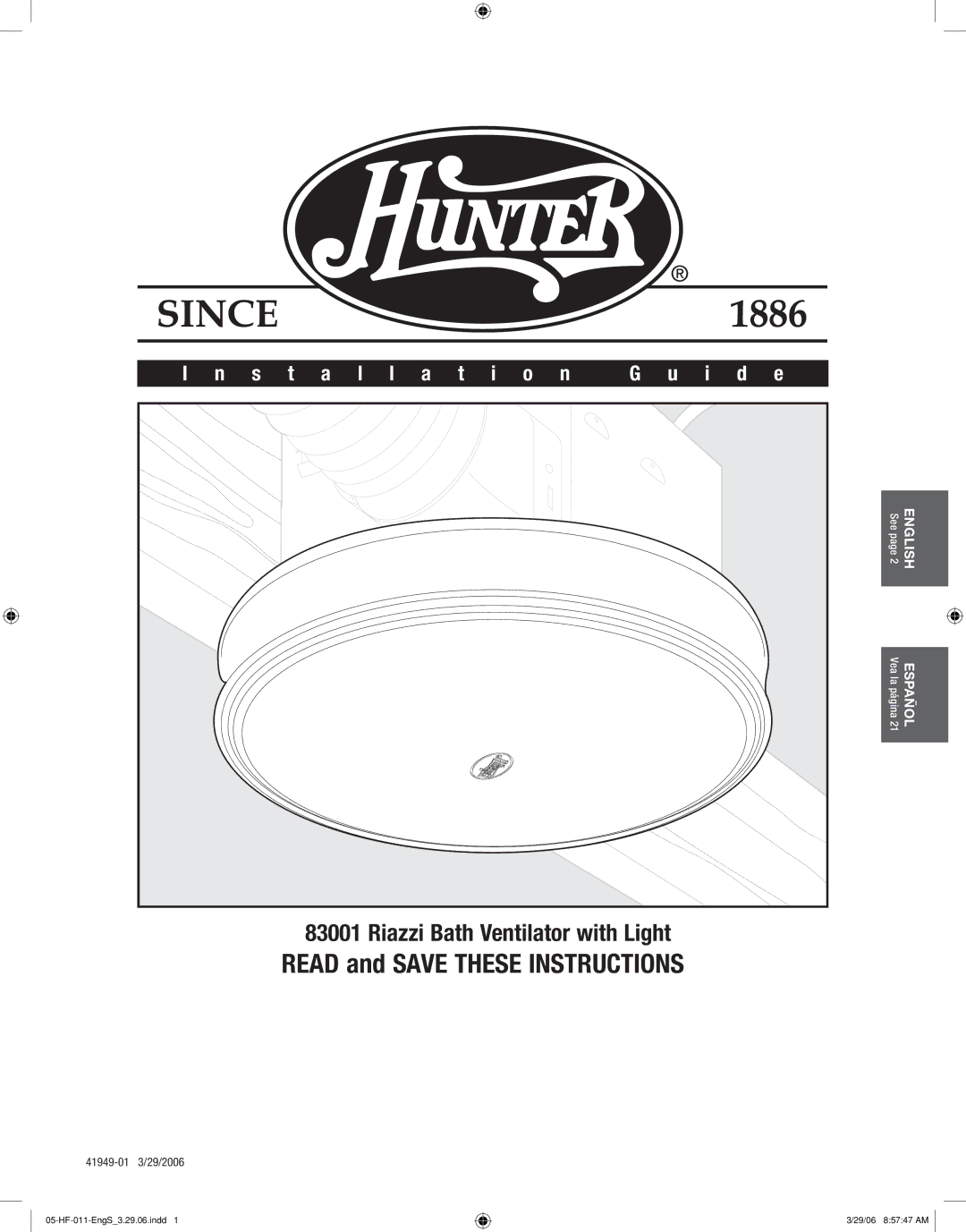
83001 Riazzi Bath Ventilator with Light
READ and SAVE THESE INSTRUCTIONS
3/29/06 8:57:47 AM
I n s t a l l a t i o n | G u i d e |
ENGLISH
See page 2
Español
Vea la página 21
83001 Riazzi Bath Ventilator with Light
READ and SAVE THESE INSTRUCTIONS
3/29/06 8:57:47 AM