FIGURE 5.

STEP 6:

NOTE:

CAUTION:

SCREWS WITH LOCKWASHERS AND

LOCTITE ON THREADS

LEAD WIRES

CANOPY

SCREW HEADGROUND WIREPIPE NIPPLE BALL

ADAPTOR

CEILING PLATE


6" MIN

CANOPY


CEILING

SCREW HOLE


PLATE HOOK


PIPE NIPPLE


FAN ASSEMBLY

CANOPY


PIPE NIPPLE


SETSCREW (TIGHTEN


SECURELY)


MOTOR

FIGURE 5A.

FIGURE 5B.

FINAL WIRING

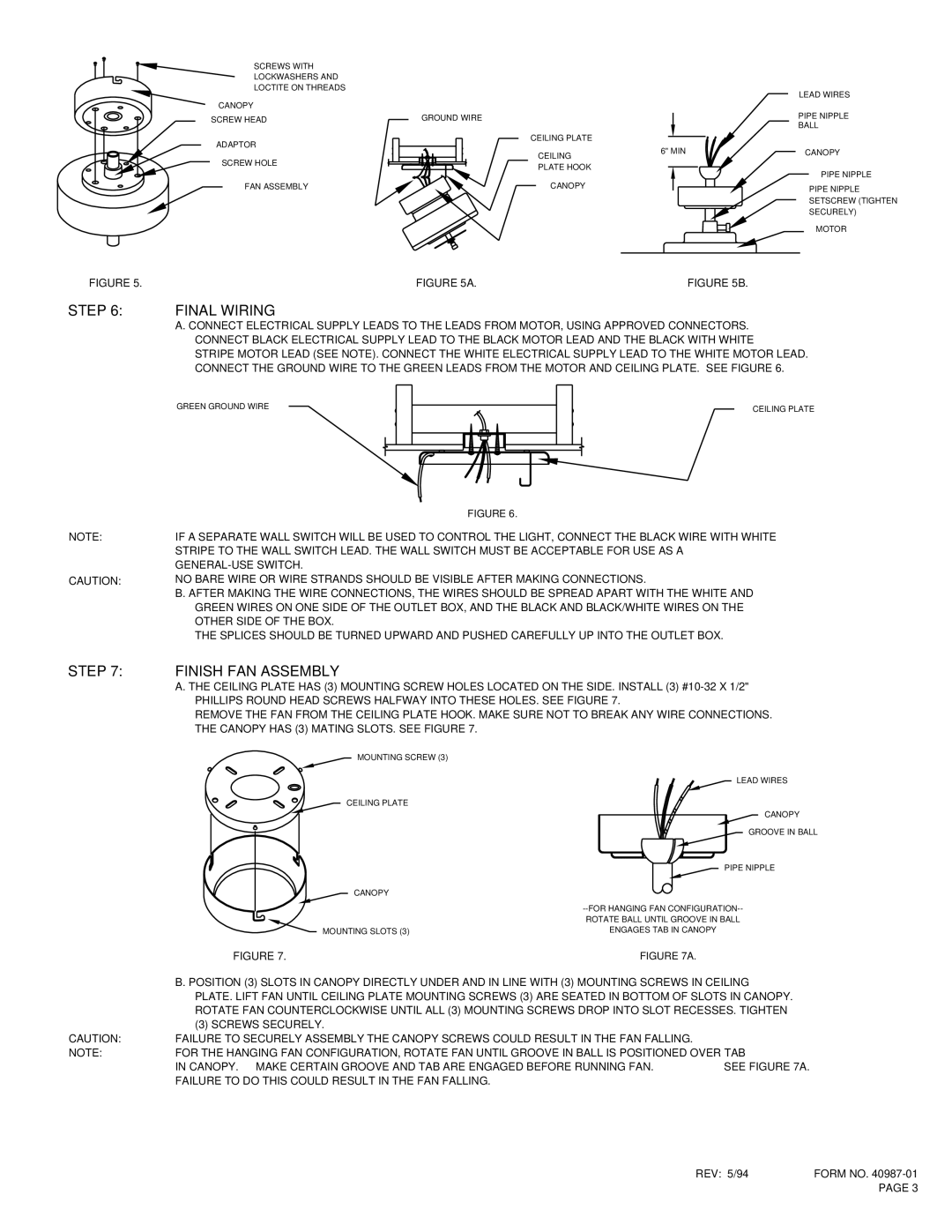
A. CONNECT ELECTRICAL SUPPLY LEADS TO THE LEADS FROM MOTOR, USING APPROVED CONNECTORS. CONNECT BLACK ELECTRICAL SUPPLY LEAD TO THE BLACK MOTOR LEAD AND THE BLACK WITH WHITE STRIPE MOTOR LEAD (SEE NOTE). CONNECT THE WHITE ELECTRICAL SUPPLY LEAD TO THE WHITE MOTOR LEAD. CONNECT THE GROUND WIRE TO THE GREEN LEADS FROM THE MOTOR AND CEILING PLATE. SEE FIGURE 6.

GREEN GROUND WIRE

CEILING PLATE


FIGURE 6.

IF A SEPARATE WALL SWITCH WILL BE USED TO CONTROL THE LIGHT, CONNECT THE BLACK WIRE WITH WHITE STRIPE TO THE WALL SWITCH LEAD. THE WALL SWITCH MUST BE ACCEPTABLE FOR USE AS A GENERAL-USE SWITCH.

NO BARE WIRE OR WIRE STRANDS SHOULD BE VISIBLE AFTER MAKING CONNECTIONS.

B. AFTER MAKING THE WIRE CONNECTIONS, THE WIRES SHOULD BE SPREAD APART WITH THE WHITE AND GREEN WIRES ON ONE SIDE OF THE OUTLET BOX, AND THE BLACK AND BLACK/WHITE WIRES ON THE OTHER SIDE OF THE BOX.

THE SPLICES SHOULD BE TURNED UPWARD AND PUSHED CAREFULLY UP INTO THE OUTLET BOX.

STEP 7: FINISH FAN ASSEMBLY

A. THE CEILING PLATE HAS (3) MOUNTING SCREW HOLES LOCATED ON THE SIDE. INSTALL (3) #10-32 X 1/2"

PHILLIPS ROUND HEAD SCREWS HALFWAY INTO THESE HOLES. SEE FIGURE 7.

REMOVE THE FAN FROM THE CEILING PLATE HOOK. MAKE SURE NOT TO BREAK ANY WIRE CONNECTIONS.

THE CANOPY HAS (3) MATING SLOTS. SEE FIGURE 7.

MOUNTING SCREW (3)

LEAD WIRES

CEILING PLATE

CANOPY


GROOVE IN BALL


PIPE NIPPLE


CANOPY


--FOR HANGING FAN CONFIGURATION--


ROTATE BALL UNTIL GROOVE IN BALL


MOUNTING SLOTS (3)

ENGAGES TAB IN CANOPY


FIGURE 7.

FIGURE 7A.


B. POSITION (3) SLOTS IN CANOPY DIRECTLY UNDER AND IN LINE WITH (3) MOUNTING SCREWS IN CEILING


PLATE. LIFT FAN UNTIL CEILING PLATE MOUNTING SCREWS (3) ARE SEATED IN BOTTOM OF SLOTS IN CANOPY.


ROTATE FAN COUNTERCLOCKWISE UNTIL ALL (3) MOUNTING SCREWS DROP INTO SLOT RECESSES. TIGHTEN


(3) SCREWS SECURELY.


CAUTION:

FAILURE TO SECURELY ASSEMBLY THE CANOPY SCREWS COULD RESULT IN THE FAN FALLING.


NOTE:

FOR THE HANGING FAN CONFIGURATION, ROTATE FAN UNTIL GROOVE IN BALL IS POSITIONED OVER TAB


IN CANOPY. MAKE CERTAIN GROOVE AND TAB ARE ENGAGED BEFORE RUNNING FAN.

SEE FIGURE 7A.


FAILURE TO DO THIS COULD RESULT IN THE FAN FALLING.


REV: 5/94

FORM NO. 40987-01


PAGE 3

Page 3
Image 3
Hunter Fan TYPE 2 installation instructions Step, Final Wiring, Finish FAN Assembly

TYPE 2 specifications

The Hunter Fan Type 2 ceiling fan stands out as an innovative and stylish addition to any home, combining aesthetic appeal with advanced engineering. Celebrated for its blend of modern design and efficient functionality, the Hunter Fan Type 2 is suitable for various spaces, from contemporary living rooms to cozy bedrooms.

One of the standout features of the Hunter Fan Type 2 is its energy-efficient DC motor, which provides powerful airflow while using significantly less energy compared to traditional AC motors. This not only helps reduce electricity bills but also contributes to a more sustainable environment. The fan operates quietly, ensuring that it enhances comfort without causing noise disruptions.

Another notable characteristic is its versatile design. The Hunter Fan Type 2 is available in multiple finishes and blade styles, allowing homeowners to choose a fan that perfectly complements their interior decor. The sleek lines and modern aesthetic make it a focal point in any room, seamlessly blending functionality with style.

Equipped with advanced technologies, the Hunter Fan Type 2 offers convenient features such as a remote control system. Users can easily adjust the fan speed, direction, and lighting from anywhere in the room, enhancing the overall user experience. The fan also comes with an integrated LED light kit, providing ample illumination while being energy efficient.

The Hunter Fan Type 2 is designed for easy installation, accommodating standard ceiling heights and providing multiple mounting options, including flush mount and downrod. This flexibility makes it accessible for various ceiling configurations, making it a great choice for both new builds and renovations.

With its robust construction, the Hunter Fan Type 2 is built to last. The high-quality materials used in its production ensure durability, while the blades are engineered for optimal airflow performance. The fan also supports reversible motor functionality, allowing for year-round use. In the summer, it can be set to create a cool breeze, while in the winter, it effectively circulates warm air.

In summary, the Hunter Fan Type 2 embodies a fusion of efficiency, style, and advanced technology. With its energy-saving DC motor, modern design options, and user-friendly features, it is an excellent choice for those seeking a reliable and aesthetically pleasing ceiling fan that meets contemporary demands.