ASSEMBLY
Assembling the loop handlebar (325C, 325CX)
• Position the handle on the shaft. Note that the handle must be mounted below the arrow on the shaft.
•Fit the bolt, securing plate and wing nut as shown in the diagram.
•Tighten the wing nut.
Assembling the loop handlebar (322L, 323L, 325LX, 325LXT, 325LDX)
• Clip the loop handle onto the shaft. Note that the loop handle must be fitted between the arrows on the shaft.
•Slide the spacer into the slot in the loop handle.
•322L/323L: Fit the nut, washer and bolt.
325LX/325LXT/325LDX: Fit the nut, knob and bolt. Do not overtighten.
•Now adjust the trimmer to give a comfortable working position. Tighten the bolt/knob.
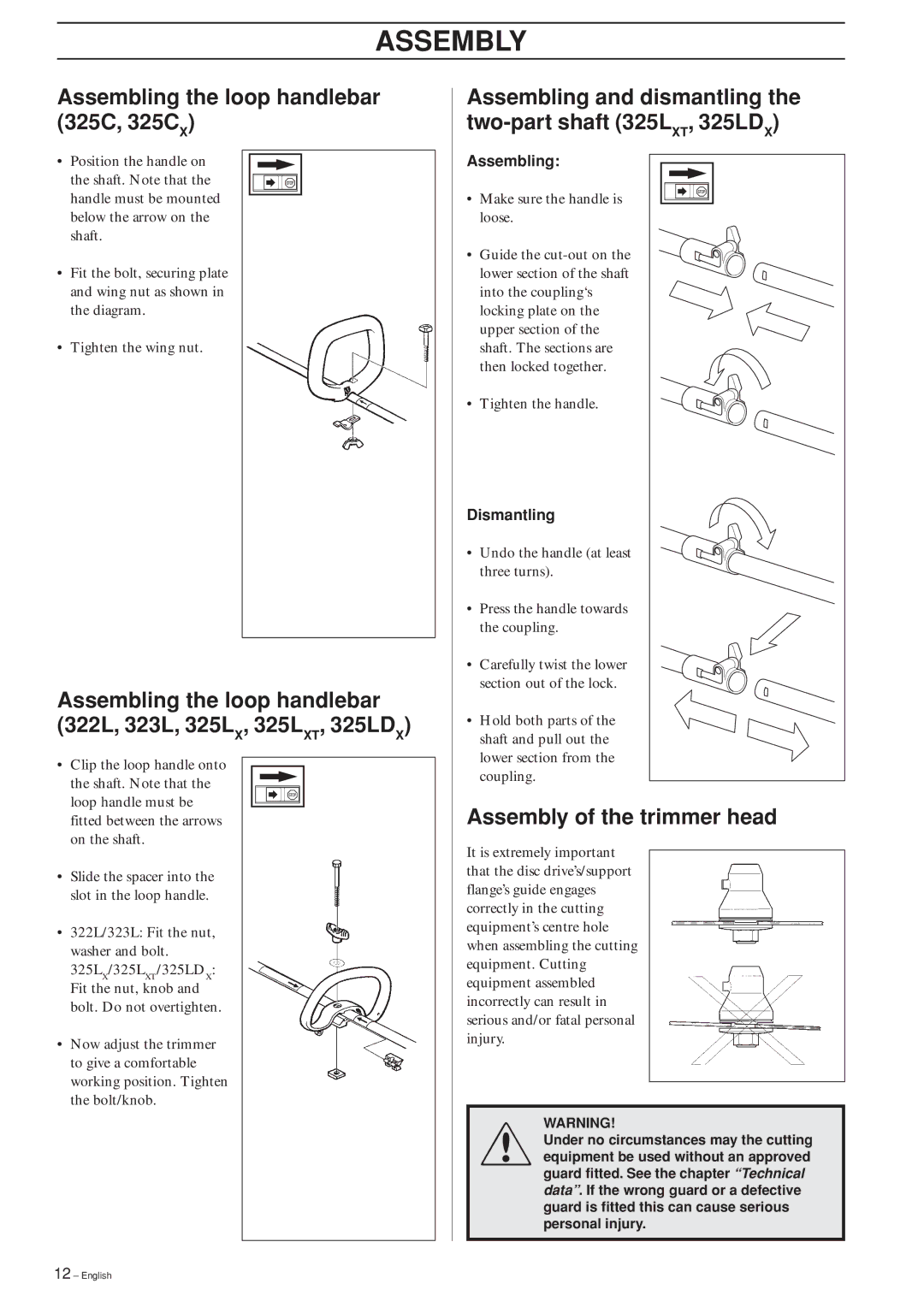
Assembling and dismantling the
Assembling:
• Make sure the handle is loose.
• Guide the
• Tighten the handle.
Dismantling
• Undo the handle (at least three turns).
•Press the handle towards the coupling.
• Carefully twist the lower section out of the lock.
•Hold both parts of the shaft and pull out the lower section from the coupling.
Assembly of the trimmer head
It is extremely important that the disc drive’s/support flange’s guide engages correctly in the cutting equipment’s centre hole when assembling the cutting equipment. Cutting equipment assembled incorrectly can result in serious and/or fatal personal injury.
!WARNING!
Under no circumstances may the cutting equipment be used without an approved guard fitted. See the chapter “Technical data”. If the wrong guard or a defective guard is fitted this can cause serious personal injury.
12 – English