ASSEMBLY
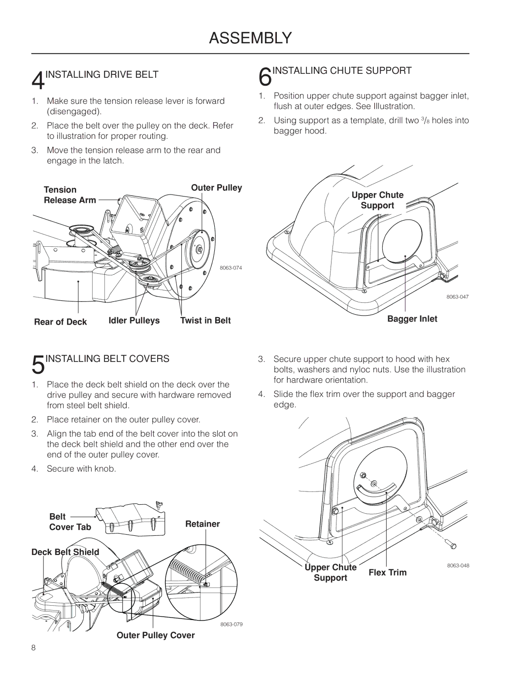
4INSTALLING DRIVE BELT
1.Make sure the tension release lever is forward (disengaged).
2.Place the belt over the pulley on the deck. Refer to illustration for proper routing.
3.Move the tension release arm to the rear and engage in the latch.
6INSTALLING CHUTE SUPPORT
1.Position upper chute support against bagger inlet, flush at outer edges. See Illustration.
2.Using support as a template, drill two 3/8 holes into bagger hood.
Tension | Outer Pulley | |
Release Arm | Upper Chute | |
Support | ||
|
Rear of Deck | Idler Pulleys | Twist in Belt | Bagger Inlet |
5INSTALLING BELT COVERS
1.Place the deck belt shield on the deck over the drive pulley and secure with hardware removed from steel belt shield.
2.Place retainer on the outer pulley cover.
3.Align the tab end of the belt cover into the slot on the deck belt shield and the other end over the end of the outer pulley cover.
4.Secure with knob.
3.Secure upper chute support to hood with hex bolts, washers and nyloc nuts. Use the illustration for hardware orientation.
4.Slide the flex trim over the support and bagger edge.
Belt | Retainer | |
Cover Tab | ||
| ||
Deck Belt Shield |
|
Upper Chute | |
Support | Flex Trim |
|
Outer Pulley Cover
8