GB
SPECIFICATIONS
Model No | .BC 435L | BC 435B |
| (965874001) |
|
Engine Type | ||
. . . . . . . . . . . . . . . . . . . . . . . . . . . . . | .Chrome Cylinder | Chrome Cylinder |
Displacement | .35 cm 3 | 35 cm 3 |
Dry Weight | .6 35Kg | 6.5Kg |
Fuel Capacity | .730 cm 3 | 730 cm 3 |
Bump Head | .Twin Line Bump Feed | Twin Line Bump Feed |
Blade 4 Teeth | .4 Teeth | 4 Teeth |
Drive Shaft Length | .66cm + 66cm | .66cm + 66cm |
Cutting Width (Twin Line Head) | .43cm | .43cm |
(Blade) | .23cm | .23cm |
Handle | .“Loop With Barrier” Handle | .“Bullhorn”Handle |
Ignition | .Electronic | .Electronic |
Drive | .Centrifugal Clutch | .Centrifugal Clutch |
Sound pressure level | .101.6 dB(A) | .101.6 dB(A) |
GB
ASSEMBLY INSTRUCTIONS
WARNING: Please install the unit according to the assembly instructions, or else it may be cause dangerous to the operator.
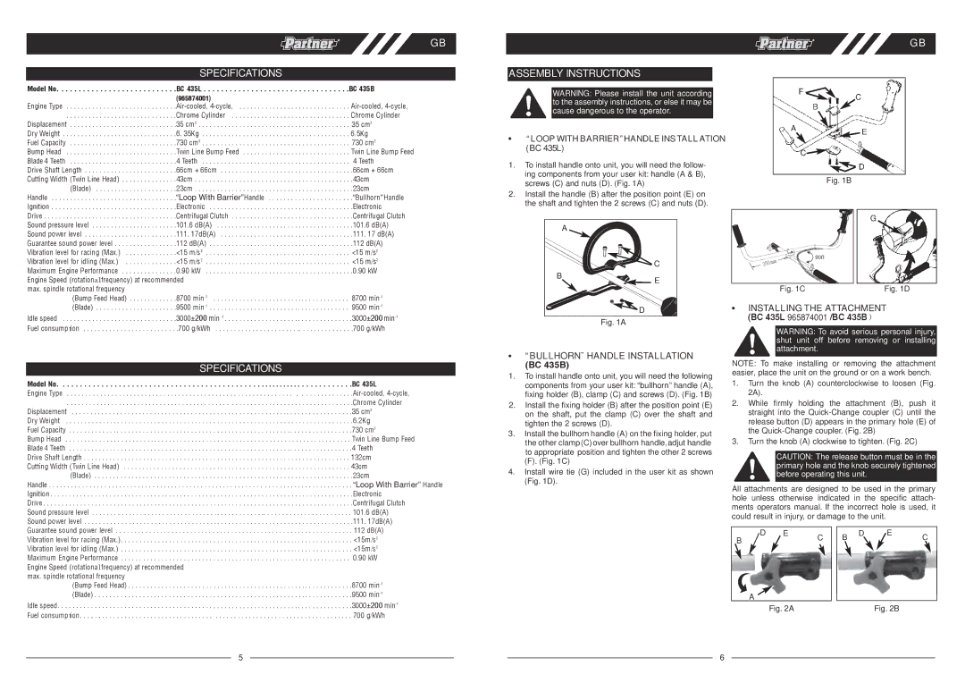
• “ LOOP WITH BARRIER ”HANDLE INSTALL ATION (BC 435L)
1. To install handle onto unit, you will need the follow- |
|
ing components from your user kit: handle (A & B), |
|
screws (C) and nuts (D). (Fig. 1A) | Fig. 1B |
|
2.Install the handle (B) after the position point (E) on the shaft and tighten the 2 screws (C) and nuts (D).
Sound power level | .111 17dB(A) | .111 17 dB(A) |
Guarantee sound power level | .112 dB(A) | .112 dB(A) |
Vibration level for racing (Max.) | .<15 m/s2 | <15 m/s2 |
Vibration level for idling (Max.) | .<15 m/s2 | <15 m/s2 |
Maximum Engine Performance | .0.90 kW | .0.90 kW |
Engine Speed (rotation alfrequency) at recommended |
| |
max. spindle rotational frequency |
|
|
(Bump Feed Head) | .8700 min | 8700 min |
(Blade) | .9500 min | 9500 min |
Idle speed | .3000 ±200 min | .3000 ±200 min |
Fuel consump t on | . .700 g/kWh | .700 g/kWh |
| SPECIFICATIONS |
Model No | . . . . . . . . . . . . . . . . . . . . . . . . . . . . . . . . . . . . .BC 435L |
Engine Type | . . . . . . . . . . . . . . .Ai |
| . . . . . . . . . . . . . . . . . . . . . . . . . . . . . . . . .Chrome Cylinder |
Displacement | . . . . . . . . . . . . . . . . . .35 cm 3 |
Dry Weight | . . . . . . . . . . . . . . . . . . . . . . . . . . . . . . . . . . . . . . . . .6.2Kg |
Fuel Capacity | . . . . . . . . . . . . . . . . . . . . . . . . . . . . . . . . . . . . . . . . .730 cm3 |
Bump Head | . . . . . . . . . . . . . . . . . . . . . . . . . . . . . Twin Line Bump Feed |
Blade 4 Teeth | . . . . . . . . . . . . . . . . . . . . . . . . . . . . . . . . . . . . . . . . .4 Teeth |
Drive Shaft Length. | . . . . . . . . . . . . . . . . . . . . . . . . . . . . . . . . . . . . . . . . 132cm |
Cutting Width (Twin Line Head). . | . . . . . . . . . . . . . . . . . . . . . . . . . . . . . . . . . . . . . . . . 43cm |
(Blade). . | . . . . . . . . . . . . . . . . . . . . . . . . . . . . . . . . . . . . . . . . .23cm |
Handle | “Loop With Barrier” Handle |
Ignition | . . . . . . . . . . . . . . . . . . . . . . . . . . . . . . . . . . . . . . .Electronic |
Drive | . . . . . . . . . . . . . . . . . . . . . . . . . . . . . . . . .Centrifugal Clutch |
Sound pressure level | . . . . . . . . . . . . .. . . . . . . . . . . . . . . . . . . . . . . . 101.6 dB(A) |
Sound power level | . . . . . . . . . . . . . . . . . . . . . . . . . . . . . . . . . . . . .111 17dB(A) |
A
![]()
![]() C
C
B
![]() D
D
Fig. 1A
•“ BULLHORN¨ HANDLE INSTALLATION
(BC 435B)
1.To install handle onto unit, you will need the following components from your user kit: “bullhorn” handle (A), fixing holder (B), clamp (C) and screws (D). (Fig. 1B)
2.Install the fixing holder (B) after the position point (E) on the shaft, put the clamp (C) over the shaft and tighten the 2 screws (D).
3.Install the bullhorn handle (A) on the fixing holder, put the other clamp (C) over bullhorn handle, adjut handle to appropriate position and tighten the other 2 screws ( F). (Fig. 1C)
4.Install wire tie (G ) included in the user kit as shown (Fig. 1D).
![]() 90ß
90ß
Fig. 1C | Fig. 1D |
•INSTALLING THE ATTACHMENT
(BC 435L 965874001 /BC 435B )
WARNING: To avoid serious personal injury, shut unit off before removing or installing attachment.
NOTE: To make installing or removing the attachment easier, place the unit on the ground or on a work bench.
1.Turn the knob (A) counterclockwise to loosen (Fig. 2A).
2.While firmly holding the attachment (B), push it straight into the
3.Turn the knob (A) clockwise to tighten. (Fig. 2C)
CAUTION: The release button must be in the primary hole and the knob securely tightened before operating this unit.
All attachments are designed to be used in the primary hole unless otherwise indicated in the specific attach- ments operators manual. If the incorrect hole is used, it could result in injury, or damage to the unit.
Guarantee sound power level | . 112 dB(A) |
Vibration level for racing (Max.) | . <15m/s2 |
Vibration level for idling (Max.) | . <15m/s2 |
Maximum Engine Performance | 0.90 kW |
Engine Speed (rotationa lfrequency) at recommended |
|
max. spindle rotational frequency | .8700 min |
(Bump Feed Head) | |
(Blade) | .9500 min |
Idle speed | .3000 ±200 min |
Fuel consump t on | . 700 g/kWh |
5
D | E | C | B | D | E | C |
B |
|
|
| |||
|
|
|
|
|
| |
A | Fig. 2A |
|
|
| Fig. 2B |
|
|
|
|
| |||
|
|
|
| |||
|
|
|
|
|
6