ASSEMBLY
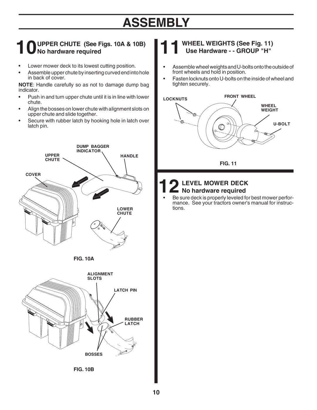
10UPPER CHUTE (See Figs. 10A & 10B) No hardware required
•Lower mower deck to its lowest cutting position.
•Assemble upper chute by inserting curved end into hole in back of cover.
NOTE: Handle carefully so as not to damage dump bag indicator.
11WHEEL WEIGHTS (See Fig. 11) Use Hardware - - GROUP "H"
•Assemble wheel weights and
•Fasten locknuts onto
•Push in and turn upper chute until it is in line with lower chute.
•Align the bosses on lower chute with alignment slots on upper chute and slide together.
•Secure with rubber latch by hooking hole in latch over latch pin.
| DUMP BAGGER |
UPPER | INDICATOR |
HANDLE | |
CHUTE |
|
LOCKNUTS
FRONT WHEEL
WHEEL
WEIGHT
COVER
LOWER
CHUTE
FIG. 10A
ALIGNMENT
SLOTS
LATCH PIN
RUBBER
LATCH
BOSSES
FIG. 10B
FIG. 11
12 LEVEL MOWER DECK No hardware required
•Be sure deck is properly leveled for best mower perfor- mance. See your tractors owner's manual for instruc- tions.
10