SERVICE AND ADJUSTMENTS
BELT INSTALLATION -
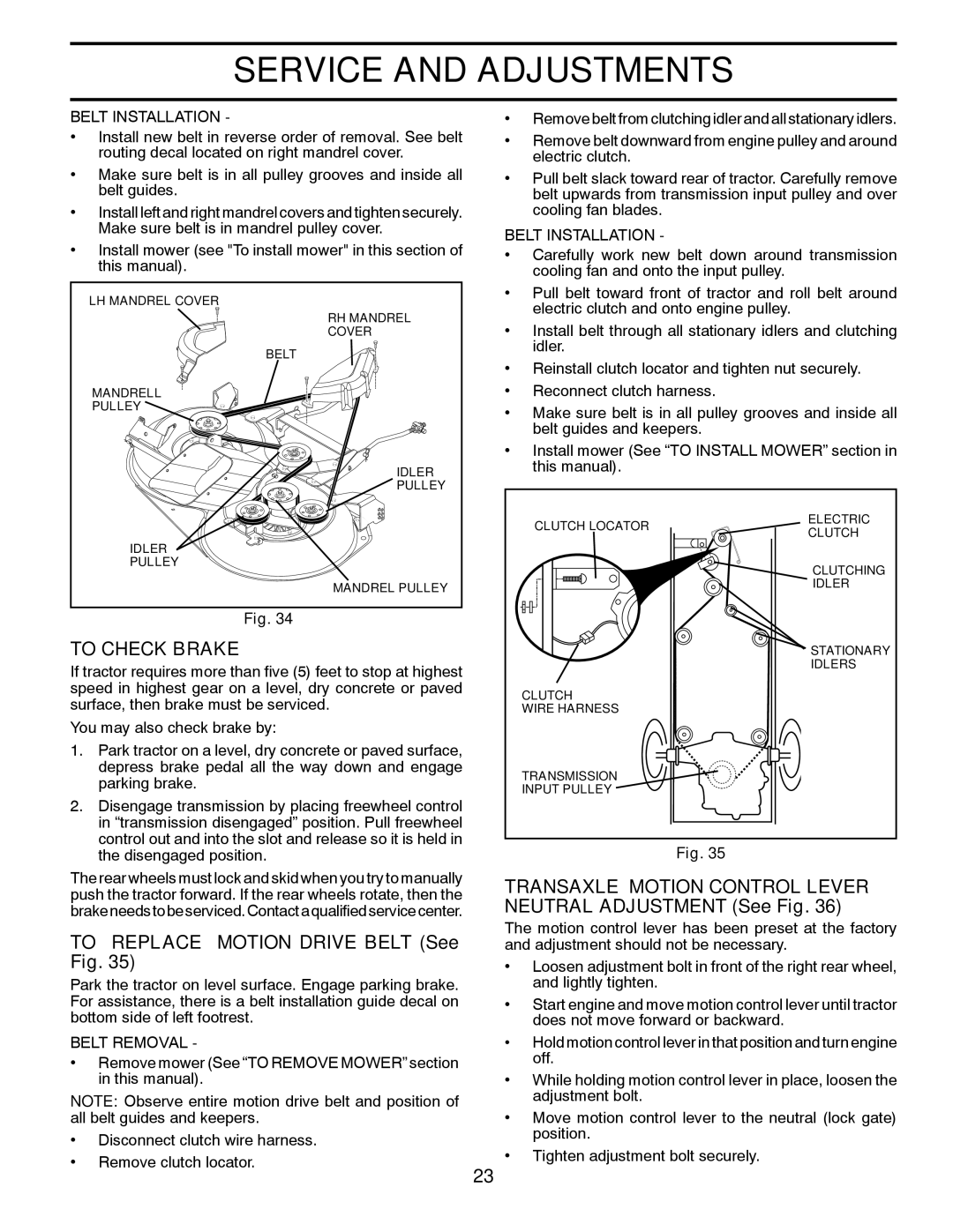
•Install new belt in reverse order of removal. See belt routing decal located on right mandrel cover.
•Make sure belt is in all pulley grooves and inside all belt guides.
•Install left and right mandrel covers and tighten securely. Make sure belt is in mandrel pulley cover.
•Install mower (see "To install mower" in this section of this manual).
LH MANDREL COVER
RH MANDREL COVER
BELT
MANDRELL
PULLEY ![]()
IDLER |
PULLEY |
•Remove belt from clutching idler and all stationary idlers.
•Remove belt downward from engine pulley and around electric clutch.
•Pull belt slack toward rear of tractor. Carefully remove belt upwards from transmission input pulley and over cooling fan blades.
BELT INSTALLATION -
•Carefully work new belt down around transmission cooling fan and onto the input pulley.
•Pull belt toward front of tractor and roll belt around electric clutch and onto engine pulley.
•Install belt through all stationary idlers and clutching idler.
•Reinstall clutch locator and tighten nut securely.
•Reconnect clutch harness.
•Make sure belt is in all pulley grooves and inside all belt guides and keepers.
•Install mower (See “TO INSTALL MOWER” section in this manual).
IDLER
PULLEY
MANDREL PULLEY
Fig. 34
TO CHECK BRAKE
If tractor requires more than five (5) feet to stop at highest speed in highest gear on a level, dry concrete or paved surface, then brake must be serviced.
You may also check brake by:
1. | Park tractor on a level, dry concrete or paved surface, |
| depress brake pedal all the way down and engage |
| parking brake. |
2. | Disengage transmission by placing freewheel control |
| in “transmission disengaged” position. Pull freewheel |
| control out and into the slot and release so it is held in |
CLUTCH LOCATOR
CLUTCH
WIRE HARNESS
TRANSMISSION INPUT PULLEY
ELECTRIC CLUTCH
CLUTCHING IDLER
STATIONARY IDLERS
the disengaged position. |
The rear wheels must lock and skid when you try to manually push the tractor forward. If the rear wheels rotate, then the brakeneedstobeserviced.Contactaqualifiedservicecenter.
TO REPLACE MOTION DRIVE BELT (See Fig. 35)
Park the tractor on level surface. Engage parking brake. For assistance, there is a belt installation guide decal on bottom side of left footrest.
BELT REMOVAL -
•Remove mower (See “TO REMOVE MOWER” section in this manual).
NOTE: Observe entire motion drive belt and position of all belt guides and keepers.
• Disconnect clutch wire harness.
• Remove clutch locator.
23
Fig. 35
TRANSAXLE MOTION CONTROL LEVER NEUTRAL ADJUSTMENT (See Fig. 36)
The motion control lever has been preset at the factory and adjustment should not be necessary.
•Loosen adjustment bolt in front of the right rear wheel, and lightly tighten.
•Start engine and move motion control lever until tractor does not move forward or backward.
•Hold motion control lever in that position and turn engine off.
•While holding motion control lever in place, loosen the adjustment bolt.
•Move motion control lever to the neutral (lock gate) position.
•Tighten adjustment bolt securely.